Chenbro SR209/105/107/108 4-Ports Mini-SAS Backplane User’s Manual 4 Ports Mini-SAS Backplane User Manual Rev. 1.0 Supplier : Chenbro Micom Co., Ltd . Description : 4 Ports Mini-SAS Backplane Chassis : SR209/SR105/SR107/SR108/RM314 Part No : 80H102209-013 http://www.chenbro.
Chenbro SR209/105/107/108 4-Ports Mini-SAS Backplane User’s Manual Copyright This document is copyrighted, 2004, by Chenbro Micom Co., Ltd. All rights are reserved. Chenbro Micom Co., Ltd. reserves the right to make improvements to the products described in this manual at any time. Specifications are thus subject to change without prior notice. No part of this manual may be reproduced, copied, translated, or transmitted in any form or by any means without the prior written permission of Chenbro Micom Co.
Chenbro SR209/105/107/108 4-Ports Mini-SAS Backplane User’s Manual Category 1 General Hard-Ware Specification 2 Backplane Layout 3 Backplane Photo 4 Backplane Cable Information 5 Backplane Ordering Information http://www.chenbro.
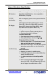
Chenbro SR209/105/107/108 4-Ports Mini-SAS Backplane User’s Manual General Hardware Specification Host Interface Mini SAS (SFF-8087) interfaces(single path) HDD Interface HDD connector (power+drive : 7+7+15 pins) for SAS (Serial Attached SCSI) drive , also compatible to SATA II drive (7+15 pins) Hot-Swap Functionality Support inrush current control and Pre Charge for drive hot-swapping (allow on line replace Hard Disk Drive) LED Display On Board LED indicates Hard Disk Drive status: Power LED – Blue
Chenbro SR209/105/107/108 4-Ports Mini-SAS Backplane User’s Manual HDD Fail and Activity Functionality supported 1. HDD activity LED source is selected by 2 x 5 pins headers “jumper setting” for : a. from pin 11 of HDD (As HDD support ) b. or external HBA Card by adapter wire 2. HDD Faulty LED “Red color”, Driven from RAID HBA Card by bellowing interface required : a. SGPIO : follow the SFF-8485 specification b.
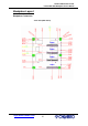
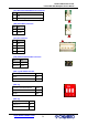
Chenbro SR209/105/107/108 4-Ports Mini-SAS Backplane User’s Manual Backplane Layout Backplane Connectors Front view (HDD slot In) CN41 CN31 CN21 CN11 http://www.chenbro.
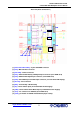
Chenbro SR209/105/107/108 4-Ports Mini-SAS Backplane User’s Manual Rear View (Host Connector In ) CN3 JC1 CN7 CN9 CN4 JP1 JF1 JM1 JF2 SW1 CN2 CN1 CN5 (1) [CN11/CN21/CN31/CN41] : 29-pins SAS HDD connector (2) [CN7] : Min-SAS Host connector (3) [CN3 /CN4] : Power connectors (4) [CN1] : External HDD Activity LED Signal Input connector (from RAID Card) (5) [CN2] : HDD Fail LED Signal Input connector (from RAID Card) (6) [CN5] : Fan/PWR/Temp.
Chenbro SR209/105/107/108 4-Ports Mini-SAS Backplane User’s Manual Pin Assignment [CN1] HDD Activity LED Connector Pin Def. HDD No. 1 External Activity LED Signal CN11 3 Input CN21 5 (Remove jumper then plug CN31 7 adapter wire to connect CN41 RAID card) 9 Key Pin 10 N/A 1&2 As HDD can support activity CN11 3&4 LED signal , using jumper to CN21 5&6 close each two pins shown CN31 7&8 left side CN41 [CN2] HDD Fail LED Connector Pin Def.
Chenbro SR209/105/107/108 4-Ports Mini-SAS Backplane User’s Manual [JP1] Redundant PSU Module Fail Connector Pin Def. 1 GND 2 Power Fail Signal (TTL Active Low) [JM1] Alarm Mute Connector Pin Def. 1 Switch - 2 Switch + [JC1] I2C Connector Pin Def. 1 SDA 2 GND 3 SCL 4 +5V [CN9] SGPIO Enable/Disable Connector Pin Def.
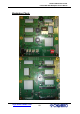
Chenbro SR209/105/107/108 4-Ports Mini-SAS Backplane User’s Manual Backplane Photo http://www.chenbro.
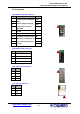
Chenbro SR209/105/107/108 4-Ports Mini-SAS Backplane User’s Manual Backplane Cable Information 1. Please refer to below compatible Mini-SAS cable for HBA HOST All of Mini-SAS cables are including SGPIO signal inside (Side Band) Item no. Description Part No. Photo Fig. No.
Chenbro SR209/105/107/108 4-Ports Mini-SAS Backplane User’s Manual 2. Please refer to below adapter cable for HDD activity LED in case HDD can’t support activity signal For Areca , 3Ware and High Point RAID Card wiring diagram : HDD LED Adapter Cable (1 x 5pins to 1 x 4pins) RAID Card HDD Pin 1 1 2 3 HDD4 3 5 HDD3 4 7 HDD2 Key Pin 9 HDD1 Cable Part No. : 26H113322-001 Compatible Chassis Model List Part No.