6-Port 6Gb/s 2.5” Mini-SAS Backplane 80H10220920A0 User’s Manual CHENBRO 6 Port 2.5” mini-SAS Backplane 80H10220920A0 April 2013 15Fl., No.150, Jian Yi Road, Chung Ho City, Taipei Hsien, Taiwan R.O.C., Tel: +886 2 82265500 Fax: +886 2 82265392 e-mail: info@chenbro.com.tw 1 w w w . c h e n b r o .
6-Port 6Gb/s 2.5” Mini-SAS Backplane 80H10220920A0 User’s Manual Copyright Copyright © 2012 Chenbro Micom Co., Ltd.. All rights reserved. Unless otherwise indicated, all materials in this manual are copyrighted by Chenbro Micom Co., Ltd.. All rights reserved. No part of this manual, either text or image may be used for any purpose other than internal using within purchasing company.
6-Port 6Gb/s 2.5” Mini-SAS Backplane 80H10220920A0 User’s Manual Contents Copyright…………………………………………………………………………………………...2 Technical Support………………………………………………………………………………….2 Contents…………………………………………………………………………………………….3 Safety Instruction…………………………………………………………………………………..4 Revision History……………………………………………………………………………………4 6 Gb/s Backplane Specification……………………………………………………………………5 Backplane Layout………………………………………………………………………………6~10 Chassis Assembly Example………………………………………………………………………11 w w w . c h e n b r o .
6-Port 6Gb/s 2.5” Mini-SAS Backplane 80H10220920A0 User’s Manual Safety Instruction Caution: Informs the user of conditions that might result in damage to hardware, corruption of customer data or application software, or long-term health hazard to people. A caution always precedes the information to which it relates. WARNINGS: Alerts the user to conditions that might result in injury or death. A warning always precedes the information to which it pertains. Revision History Date Jan. 11, 2013 Apr.
6-Port 6Gb/s 2.
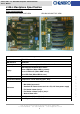
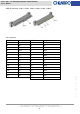
-Port 6Gb/s 2.5” Mini-SAS Backplane 80H10220920A0 User’s Manual Backplane Layout Fan Connector (JF1~JF2) Pin NO. Description 1 GND 2 12V 3 FAN Clock Input Power Fail Alarm Connector (JP1) Pin Description NO. 1 GND 2 Fall signal Input (Active Low) Power Fail Mute Connector (JM1) Pin Description NO. 1 MUTE- 2 MUTE+ Pin No. Descriptions 1 12V 2 GND 3 GND 4 5V CN05 CN06 15Fl., No.150, Jian Yi Road, Chung Ho City, Taipei Hsien, Taiwan R.O.C.
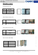
6-Port 6Gb/s 2.5” Mini-SAS Backplane 80H10220920A0 User’s Manual HDD Display Connector - 2.54 Pin Header (CN08) Pin NO. Description Pin No. Description 1 FAILED LED + 2 NC 3 FAILED LED- 4 MUTE SW+ 5 KEY PIN 6 MUTE SW- HDD Failed LED Connector (CN01) Pin NO. Description 1 HDD FAILED LED (CN11) 2 HDD FAILED LED (CN21) 3 HDD FAILED LED (CN31) 4 HDD FAILED LED (CN41) HDD Failed LED Connector (CN02) Pin NO.
6-Port 6Gb/s 2.5” Mini-SAS Backplane 80H10220920A0 User’s Manual MINI SAS Connector (CB1~CB2) Top view Pin assignment Pin NO. Descriptions Pin NO.
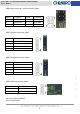
6-Port 6Gb/s 2.5” Mini-SAS Backplane 80H10220920A0 User’s Manual HDD IN Connector (CH011, CH021, CH031, CH041, CH051, CH061) Pin assignment Descriptions Pin NO. Descriptions S1 GND P1 NC S2 RP P2 NC S3 RN P3 NC S4 GND P4 GND S5 TN P5 POWER ENABLE S6 TP P6 GND S7 GND P7 5V PRE- CHARGE S8 NC P8 5V S9 NC P9 5V S10 NC P10 GND S11 NC P11 ACCESS SIGNAL S12 NC P12 GND S13 NC P13 12V PRE- CHARGE S14 NC P14 12V P15 12V 15Fl., No.
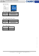
6-Port 6Gb/s 2.5” Mini-SAS Backplane 80H10220920A0 User’s Manual SW1 FUNCTION SW1-1: FAN1 Enable/Disable Setting SW1-1 FAN1 ON Enable (Default) OFF Disable SW1-2: FAN2 Enable/Disable Setting SW1-2 FAN2 ON Enable OFF Disable (Default) SW1-3: TEMP Setting SW1-3 TEMP ON 65℃ OFF 55℃(Default) w w w . c h e n b r o . c o m 15Fl., No.150, Jian Yi Road, Chung Ho City, Taipei Hsien, Taiwan R.O.C., Tel: +886 2 82265500 Fax: +886 2 82265392 e-mail: info@chenbro.com.
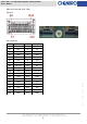
6-Port 6Gb/s 2.5” Mini-SAS Backplane 80H10220920A0 User’s Manual Backplane Wiring Connect to Power supply Link to RAID card For manufacturer only For manufacturer only RAID Card Link to chassis LED board R.PSU 2x FAN Mini SAS cable (BP to Host, 2x cables per BP) Fan (3P3C) 2-pin PSU Failure LED & Alarm Mute Cables (BP to Front Panel LED Display) R.PSU alarm signal connectors that fitting to Chenbro Mute backplane. TTL 15Fl., No.150, Jian Yi Road, Chung Ho City, Taipei Hsien, Taiwan R.O.C.