Manual Part No. 0G3865 1.
foreword This manual has been published by GENERAC® POWER SYSTEMS, INC. to aid our dealers’ mechanics, company service personnel and general consumers when servicing the products described herein. It is assumed that these personnel are familiar with the servicing procedures for these products, or like or similar products, manufactured and marketed by GENERAC® POWER SYSTEMS, INC.
1.6 Liter Gas Engine Table of Contents service recommendations . .................................................................................................................... 2 Chery Contents.................................................................................................................................................. This engine has been engineered for use in Generac Power Systems products.
1.6 Liter Gas Engine Service Recommendations ◆ Engine Oil Recommendations Do not remove the radiator pressure cap while the engine is hot or serious burns from boiling liquid or steam could result. * The unit has been filled with “break in” engine oil at the factory. Use a high-quality detergent oil classified “For Service CC, SD, SE or SF.” Detergent oils keep the engine cleaner and reduce carbon deposits.
1.6 Liter Gas Engine Service Recommendations 8 kW - 35 kW Small Standby Generator Sets Following is a recommended maintenance schedule for Generac small standby and residential generator sets from 8 kW to 35 kW in size, and applies to both diesel engine and gas engine driven units. The established intervals in the schedule are the maximum recommended when the unit is used in an average service application.
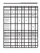
Liter Gas Engine Service Recommendations Maintenance Tasks Level 1 Recommended to be done monthly/ 10 hrs. Level 2 Task Comp. (DateInitials) Level 3 Required to be done 3 months/ Break-in /30 hrs. Task Comp. (DateInitials) Required to be done SemiAnnually/50 hrs. Level 4 Task Comp. (DateInitials) Required to be done Annually/ 100 hrs. 1. Disable the unit from operating per the first page warning. • • • • 2. Check the engine oil level. Adjust as necessary. • • • • 3.
1.6 Liter Gas Engine Service Recommendations Maintenance Tasks Level 1 Recommended to be done monthly/ 10 hrs. 14. Visually inspect the unit looking for leaks, wear or damage, loose connections or components, and corrosion. Correct as necessary. • Level 2 Task Comp. (DateInitials) Level 3 Required to be done 3 months/ Break-in /30 hrs. • Task Comp. (DateInitials) Required to be done SemiAnnually/50 hrs. • 15. Test the engine and transfer switch safety devices. Correct and/or adjust as necessary.
Notes
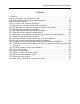
Engine Maintenance And Servicing Manual Catalogue Introduction………………………………………………………………………………………1 Engine configuration view and sectional view………………………………………………… 3 Main engine technical indexes and operation parameters………………………………………11 Engine structural features………………………………………………………………………13 Engine removal and assembly procedure………………………………………………17 [1] Positioning no.
Engine Maintenance And Servicing Manual Introduction CAC478, CAC480 series vehicle gasoline engines, which are the products introduced from Ford (Britain) corporation CVH production line, are made by Anhui Chery automobile Corp. Products are made up of carburetor type, single-point electric control fuel injection type and electric control fuel injection type, which may meet the requirements for different performance and emission.
Engine Maintenance And Servicing Manual 1.Temperature regulator seat assembly 2.Temperature regulator seat 3. Distributor 4. Camshaft assembly 5. Fuel pump assembly 6. Air intake manifold assembly 7. Fuel pressure switch 8. Oil filter assembly 9. Rear oil sealing carrier assembly 10. Oil collector assembly 11. Camshaft thrust plate 12. Camshaft timing gear 13. Timing belt 14. Upper\ lower timing gear cap assembly 15. Water pump assembly 16. Camshaft timing gear 17. Tensioner pulley assembly 18.
Engine Maintenance And Servicing Manual Main engine technical indexes and operation parameters SQR480 Type Line, 4-cyl, four strokes, water-cooling Cylinder bore diameter (mm) 79.94 Stroke (mm) 79.52 Total displacement (L) 1.596 Compression ratio 9.
Engine Maintenance And Servicing Manual Application parameters Lubricant (With temperature at - 50°F or more) SAE10W/30-50( grade SF) Engine oil pressure Idling 14.5 psi (min) Engine oil pressure @ 2000 rpm (176°F) 40.6 psi (min) Engine oil capacity 1.
Engine Maintenance And Servicing Manual Engine structural features 1.Cylinder block:Made from gray cast iron. Without bibcock. Without cylinder liner.5 main bearing seats. Main Intermediate bearing anti-thrust. Main bearing caps are retained by spigot. Main bearing bolts of 12.9 grade. 2.Cylinder head:Made from aluminum alloy. Intake and exhaust valve seats and valve guides strutting.6 camshaft supports. Without camshaft bushing.
Engine Maintenance And Servicing Manual 19.Intake manifold:Made from Aluminum alloy. With mixture warm upped by water jacket. Electric heated intake manifold is optional. 20.Exhaust manifold:Made from ductalloy or black cast iron. 21.Oil pan:Stamping ,Low carbon steel. Oil pool is in the front of cylinder block. 22.Oil pump:Rotor type. Case is made of aluminum alloy. Speed ratio 1∶1,With pressure relief valve in oil pump. 23.Engine oil filter:Full flows type spinning filter. With by-pass valve in it. 24.
Engine Maintenance And Servicing Manual Engine removal and assembly procedure 【1】. Positioning no.1 cylinder top dead center (compression) ——Remove two M6×55 flange-shaped bolts, remove upper timing gear cover. ——Install a wrench on crankshaft pulley bolt, rotate crankshaft Clockwise (viewed from the direction of pulley) until the TDC notch on crankshaft pulley aligns with the TDC mark (0) on timing gear cover. Note:Before rotation,spark plugs may be removed to reduce effort. Fig.1 Fig.
Engine Maintenance And Servicing Manual 【2】. Upper and lower timing gear cover assemblies removal and installation Upper timing gear cover assembly Removal: ——Loosen and remove 2 bolts for upper timing gear cover assembly. ——Remove upper timing gear cover and seal assembly. Bolt ——Remove seal gasket and shot nail from upper timing gear cover. Tightening ——Remove crankshaft pulley. torque ——Loosen and remove 2 bolts for lower timing gear cover assembly.
Engine Maintenance And Servicing Manual Installation: ——Clean pulley and crankshaft journal,remove the oil in pulley groove . ——Install pulley on crankshaft journal, aligning keyway with semicircular key. ——Slip cushion block onto bolts and finger screw in. ——Block flywheel ring gear with screwdriver, preventing crankshaft from turning. ——Tighten bolts to 100—115Nm. Fig.6 Bolt Tightening torque Pulley Fig. 7 【4】.
Engine Maintenance And Servicing Manual Installation: ——Clean cylinder head and valve cover contacting surface. ——Push the wedge of valve cover seal gasket into appropriate valve cover groove, integrating valve cover with seal gasket. Fig.9 ——Install valve cover and seal gasket assembly on cylinder head. ——Install 9 hexagon head bolts of long column end with butterfly gasket,finger screw them into cylinder head. ——Tighten bolts in two steps in order as diagram showed. Step 1:Tighten to 4.0—6.
Engine Maintenance And Servicing Manual Note:With belt removed, don't turn gear excessively,or piston head and valve may be damaged for contacting. ——If belt need to be reused ,check for improper wear ,delaminate crack (particularly at the foot of teeth) or dirt. If lightly suspected, replace it. Installation and adjustment: ——Crankshaft should be positioned at no.1 cylinder TDC,if necessary, crankshaft may only be turned slightly for adjustment and blocked at flywheel ring gear. Fig.
Engine Maintenance And Servicing Manual 【6】. Tension pulley, crankshaft gear and camshaft gear removal, check and installation 1. Tension pulley Timing gear Removal: ——Rotate crankshaft to no.1 cylinder compression TDC. ——Remove belt. Cushion ——Loosen 2 tension pulley mounting bolts, push tension pulley aside to release belt tension Key with a large screwdriver. ——Remove 2 mounting bolts and take out Bolt M12*1.5*30 tension pulley. Tightening torque52-60n.
Engine Maintenance And Servicing Manual Installation: ——Check gear tooth for wear, pitting or scratch. ——Install camshaft semicircular key,protrusion should be 1.64—2.11mm. ——Install camshaft gear on camshaft with new bolt though cushion block,new bolt should be pre-pasted and tightened to 52—60Nm. ——Check whether crankshaft is positioned at compression TDC. 3.Crankshaft gear Removal: Fig.17 ——Block crankshaft and remove belt.
Engine Maintenance And Servicing Manual 【8】. Valve mechanism and cylinder head removal, check and installation 1.Valve mechanism for 478 and 480 engine: Rock arm nut-8. tightening torque 25-29n.m Rocker arm-8 Rocker arm seat-8 Rocker arm seat washer-8 hydraulic lifting rod-8 Valve locking piece-16 Fit clearance 0.023/0.
Engine Maintenance And Servicing Manual 2.Cylinder cover bolts removal and cylinder head assembly installation Cylinder head bolts removal: ——Rotate camshaft until keyway is rightly upside. ——Loosen cylinder cover bolts in order as specified in diagram. ——Note:Cylinder cover bolts must be replaced after removed and are not permitted to reuse. Fig.20 Cylinder head assembly reinstallation: ——Check whether cylinder head contact surface roughness is 0.15mm or less. Fig.21 Fig.
Engine Maintenance And Servicing Manual ——Install new cylinder head bolts and washers into bolt holes, screw in by hand. Fig.24 ——Tighten cylinder head bolts in four steps in the order as diagram specified. Step 1:Tighten to 22 ft-lbs Step 2:Tighten to 37 ft-lbs Step 3:Rotate 90° Step 4:Rotate 90° During rotating, torque- angle torque wrench or line plotting methods may be applied. Fig.25 3.
Engine Maintenance And Servicing Manual Installation: ——Check rocker arm contact surface for abnormal wear, replace rocker arm if necessary. ——Pull rocker arm support washers onto rocker arm double end studs. ——Lubricate rocker arms and rocker arm supports with engine oil. ——Install rocker arm, rocker arm support,then finger screw in new nut, tighten to 20 ft-lbs. Fig.28 Note:Before installing each rocker arm and tightening nut, appropriate hydraulic lifting rod should be at the lowest position. Fig.
Engine Maintenance And Servicing Manual Hydraulic lifting rod installation: ——Hydraulic lifting rod size: Grade Lifting rod outside diameter Cylinder head lifting rod hole diameter clearance Standard Φ22.200—Φ22.212 Φ22.25±0.015 0.023—0.065 T25 Φ22.454—Φ22.466 Φ22.50±0.015 0.023—0.065 Fig.31 ——Apply hyperbolical gear lubricant or engine oil on lifting rod, lifting rod outside diameter and lifting rod ends, install lifting rods in original order into the holes in the cylinder head. 4.
Engine Maintenance And Servicing Manual ——Camshaft journal and cylinder head cam bearing hole size: (1) Standard size mm Fig.35 Camshaft journal number Camshaft journal diameter Cylinder head bearing hole diameter 1 44.74—44.76 44.783—44.808 2 44.99—45.01 45.033—45.058 3 45.24—45.26 45.283—45.308 4 45.49—45.51 45.533—45.558 5 45.74—45.76 45.783—45.808 (2). Over size (0.
Engine Maintenance And Servicing Manual 5.Valve, valve spring, valve oil seal, spring seat assembly removal and Fig.38 installation: Removal: Using special tools for valve compression, take out valve locking pieces, don't compress spring excessively, compress spring enough to slip locking pieces out of its stroke, or valve stem may be bent.
Engine Maintenance And Servicing Manual ——Measure valve spring free length and spring force: Fig.42 Fig.42 Compression (mm) Spring load (N) L1=37.084 422 L2=27.7 892.7 L3=27.0 945 Spring free length L0=47.2 ——Grinding the valve and the valve seat with the valve conical angle (Intake valve and exhaust valve): 44°30′— 45°30′ Valve seat sealing width: 1.75 — 2.32mm Fig.43 Fig.
Engine Maintenance And Servicing Manual 6.the sizes for intake valve, intake valve seat, exhaust valve seat and valve guide The size of intake valve seat and cylinder head valve seat hole Diameter of intake valve seat Diameter of the cylinder head valve seat hole Standard 478 41.877+0.01 -0.01 41.763+0.025 0 Oversize 0.5 42.377+0.01 -0.01 42.263+0.025 0 Oversize 1.0 42.877+0.01 -0.01 42.763+0.025 0 Standard 480 43.877+0.01 -0.01 44.763+0.025 0 Oversize 0.5 44.377+0.01 -0.01 44.263+0.
Engine Maintenance And Servicing Manual 【9】. Removal and installation of the piston and rod assembly Removal: ——Remove the crankshaft to the bottom dead center of the cylinder. Check and make sure that there is a cylinder mark on the connecting rod and its cap. or make a mark on each cylinder before removal. ——Remove the connecting rod bolts and remove the rod cap. Take the connecting rod bushing out and stick on cylinder marks and labels on the upper or lower halves.
Engine Maintenance And Servicing Manual Unit: mm 480E *dia. of piston skirt (mm) 1 79.915 – 79.925 2 79.925 – 89.935 3 79.935 – 79.945 4 79.945 – 79.955 A 80.205 – 80.215 B 80.215 – 80.225 C 80.225 – 80.235 Standard 79.965 – 79.975 Oversize 0.29 80.245 – 80.255 Oversize 0.5 80.465 – 80.475 Factory group Factory repair Spare parts Fig.51 * 480M piston should be applied on 480E engine – Measure the diameter.
Engine Maintenance And Servicing Manual Fig.53 ——Check and make sure that the oil injection hole of the connecting rod large end is not blocked. The outside diameter is φ1mm. Installation: ——Need not to divide into groups for the piston weight, piston pin holes and the accessory piston skirt. Before assembling, check the piston head mark and make sure that it is in accord with cylinder No.4.
Engine Maintenance And Servicing Manual Installation of the piston and rod assembly: Apply engine oil on piston, piston ring and cylinder bore. Stagger 120°among the first compression ring, the second ring and oil ring cotter, then install piston rod into cylinder bore. push the piston an rod assembly by hammer into the cylinder bore. ——Apply engine oil on the connecting rod bushing. Mount connecting rod cap. Retain connecting rod body and cap with two elastic retaining pins.
Engine Maintenance And Servicing Manual 2). The removal and installation of carrier assembly of the real oil seal: Removal: ——Remove 4 bolts (as arrow indicates). ——Take out carrier assembly of the real oil seal ——Remove carrier sealing gasket of the real oil seal Fig.58 Fig.59 ——Use chisel or screwdriver to pry the real oil seal from the carrier of the real seal oil. Note: please don’t damage the carrier of real oil seal.
Engine Maintenance And Servicing Manual ——Tighten four M6 bolts to 8.0 —11.0Nm。 ——Remove the plastic piece. Sealing plate M6 bolt×20(4) Tighten torque 8~11Nm Fig.62 【11】. Removal and installation crankshaft, crankshaft thrust washer, halves and main bearing cap Removal: ——Before removing, check the end play of crankshaft first. Use the plunger of dial indicator to contact bearing face of the crankshaft (lightly compressing). Push the crankshaft away from the contacting tip.
Engine Maintenance And Servicing Manual carefully. Arrange them according to the sequence. Read the bearing clearance according to the proportion stated in the cover of plastic clearance gauge. Check the bearing clearance from the third main bearing and extending to the two sides. The clearance of main bearing is 0.011—0.058m m. ——Check clearance of connecting rod bearing Use the above method to check clearance of connecting rod bearing. Clearance of connecting rod bearing is 0.006—0.06mm.
Engine Maintenance And Servicing Manual —the size of crankshaft thrust, thrust washer and cylinder block thrust: Unit:mm Level Two thrust pieces Standard Oversize 0.38 Fig. 68 The size of cylinder body thrust 24±0.03 24±0.03 The size of crankshaft thrust The thickness of thrust washer 28.825—28.875 2.326±0.025 29.205—29.255 2.516±0.
Engine Maintenance And Servicing Manual ——Nine main bearing bolts are hex head flange side bolts, and one is stud. For horizontal engine, the stud is mounted in the left threaded hole of the second main bearing cap (see from the front) which is for installing the carrier of oil collector. For the vertical engine, it should be mounted on the left threaded hole of the forth main bearing cap (see from the front).
Engine Maintenance And Servicing Manual 【13】. Engine oiling system: 1). The description of the oiling system: 1. 2. 3. 4. 5. Through oil collector (2), the rotary oil pump (1) which is installed in the front end of crankshaft draws oil from oil pan (3) and pressurizes. The pressure oil comes into the full flow type oil filter through the assistant oil passage (4) on the left of cylinder body (viewed from the front).
Engine Maintenance And Servicing Manual 2) The removal and installation of oil pan: Removal: ——Loosen drain plug and drain oil ——Loosen eighteen M6×20 bolts ——Take out the sealing gasket of oil pan ——Check if the left and right reinforced plates are still clipped on the back face of oil pan flange face Fig. 73 A. B. Crankshaft to oil pump shell Crankshaft to rear oil seal carrier Fig.
Engine Maintenance And Servicing Manual The removal and installation of oil collector assembly Removal: ——Loosen locknut of oil collector assembly and take out the nut and flat washer ——Loosen carrier bolts and take out the bolts。 ——Loosen flange face bolt of oil collector (two ) and take out the two bolts with spring washers Fig.
Engine Maintenance And Servicing Manual 4. The removal and installation of oil pump with oil seal assembly removal: ——Loosen six M6×30 hexagonal flange surface bolts. Remove the bolts (as the figure indicates) ——Remove oil pump with oil seal assembly Fig. 79 ——Pry out the front oil seal of crankshaft by screwdriver or chisel. Note: Don’t damage the front oil seal bore. ——Remove seven M6 countersunk head screws (as the arrow in figure indicates) ——Remove oil pump cover Fig.
Engine Maintenance And Servicing Manual ——Check the clearance between outer rotor of oil pump and case bore of oil pump. The clearance between outer rotor of oil pump and case bore of oil pump should be 0.06—0.19mm. Fig. 83 ——Check the radial clearance between inner rotor and outer rotor of oil pump. The radial clearance between inner rotor and outer rotor of oil pump should be 0.05—0.18mm. ——Check the end play of rotor The end play of rotor should be 0.014—0.100mm. Fig.
Engine Maintenance And Servicing Manual ——If relief valve spring is not to specification, it must be replaced. Fig. 87 Fig. 88 Installation: ——Install the outer and inner rotor into the oil pump house ensuring the installation mark of outer and inner rotor upward. ——Install oil pump cover on oil pump. Tighten seven chamfer head screws. Tightening torque is 79 in-lbs. ——Install relief valve and relief valve spring into the oil pump bore. ——Screw 3/8″plug screw into the oil pump house. Keep it in place.
Engine Maintenance And Servicing Manual ——Remove the thin plastic protective tape Fig. 91 5. Removal and installation of oil filter and oil pressure sensor. Removal: ——Remove the oil filter. Rotate oil filter counterclockwise during removal. ——Remove the oil pressure sensor Installation: ——Apply engine oil on the sealing gasket of oil filter and screw into the connector. Tightening torque is 12-17Nm. Or screw into oil filter by hand.
Engine Maintenance And Servicing Manual 【14】. Hose Engine cooling system 1) Description for cooling system Warm wind Expansion The cooling system is of pressure system. It heat exchanger Pressure tank includes water pump driven by timing belt, cap crosscurrent radiator, expansion tank, pressure Hose Hose cap, thermostat and electric fan, fan shroud. Hose Hose Water pump inlet Engine Coolant pipe assembly Water temperature sensor Hose assembly Electric fan Radiator Fig.
Engine Maintenance And Servicing Manual ——Coolant draining : (1) Remove pressure cap of expansion water tank (2) Connect a container under the radiator. Remove the outlet hose of radiator or open the drain plug of radiator. ——Cleaning cooling system: (1) Drain the coolant and then close the drain plug of radiator or install the outlet hose of radiator (2) Add clean water into the max water level of expansion tank and install the pressure cap (3) Start engine and keep idling.
Engine Maintenance And Servicing Manual 2) The removal and installation of water pump assembly ——The structure of water pump assembly 1—water pump case 2—water pump impeller 3—water pump gear 4—water pump bearing 5—water pump seal (ceramics—black lead) Fig.
Engine Maintenance And Servicing Manual 3) The removal and installation of thermostat seat with thermostat assembly ——Loosen three M6×40 bolts and remove them ——Remove thermostat seat with thermostat assembly ——Pry out spring clip by chisel or screwdriver Fig.96 ——Take out the thermostat ——Take out sealing gasket ——Remove sealing gasket of thermostat seat Fig. 97 Measure the opening temperature of thermostat in hot water. Fig. 98 Fig. 99 PDF 文件使用 "pdfFactory Pro" 试用版本创建 www.fineprint.com.
Engine Maintenance And Servicing Manual Thermostat Spring clip Sealing gasket Sealing gasket Overflow pipe Drainage pipe Sealing gasket Small recirculating pipe Temperature seat assembly Tighten torque Plug screw Fig.100 Assembly: ——Clip the thermostat seat, and put the rubber seal ring into the thermostat hole. ——Install the thermostat (with spring outward) ——Install spring clip, ensure that the clip is clipped in the thermostat seat groove.
Engine Maintenance And Servicing Manual ——The air filter is equipped with a intake air temperature controller. When the temperature is low, the hot air intake valve controlled by the temperature controller will open and the hot air, flowing by the exhaust manifold, will be directed into the air filter from the intake preheating hose to supply more hot air and facilitate the fuel atomization during cold winter.
Engine Maintenance And Servicing Manual The intake manifold ‘s air may be preheated by the electrical heater as well as by coolant. As the coolant’s temperature is lower than 60°, the electronic heater will be energized to facilitate the cold starting. The electrical heater’s energizing or deenergizing is controlled by the intake preheating switch and relay. The intake preheating switch is installed in the M22 bolt hole in the thermostat seat(with the hole plugged by plug screw for carburetor engine).
Engine Maintenance And Servicing Manual 4. The removal and assembly for the exhaust manifold, heat insulation cover and rear lifting lug: Bolt Removal: -Loose and remove the M12×25 allen screw, and remove the rear lug . -Loose and remove two M8×12 screw and remove the heat insulation cover . -Loose and remove 8 M8 lock nuts and washers.- remove the exhaust manifold. - Remove the exhaust manifold sealing gasket. - Water temp. Remove eight M8 studs of same length.
Engine Maintenance And Servicing Manual Chamber cover cap 【16】 Positive Crankcase Ventilation(PCV)system of engine. 1. Description for PCV system of the Carburetor engine: PCV system is a closed system. The leaking air of piston from the Crankcase goes to the cylinder head cover through the PCV hose. The exhaust gas enters Connection hose the intake manifold passing the 3-way pipe after throttled by the Connection hose absolute pressure pipe connector.
Engine Maintenance And Servicing Manual To intake manifold From crankcase The operation condition of low speed-high vacuity 2.2 PCV valve’s function: Under the low speed condition, the vacuum of intake manifold is very high, which keep the valve closed, and only a small opening exists to allow the gas pass through. Therefore it won’t change the mixture rate.
Engine Maintenance And Servicing Manual ——Remove the studs of same length. Assembly: ——Submerge the push rod into the engine oil or pour engine oil into the rod’s hole of the cylinder head and install the push rod into the hole. The gap between push rod and hole is 0.035-0.055mm. ——Screw in the studs into the threaded hole and tighten with the nuts. ——Install fuel pump with the manufacturer mark and part number forward. ——Tighten the lock nuts with hands. Tightening torque is 14-18Nm. Fig.
Engine Maintenance And Servicing Manual 【18】 Engine electrical system. The electrical system includes battery, alternator, starter, breakerless distributor, ignition controller, spark plug, high-power ignition coil, high pressure assembly, water temperature sensor, oil pressure switch, electric fan, thermo switch, and idle speed solenoid valve of carburetor. 1. Alternator.
Engine Maintenance And Servicing Manual The JFZ1913—4 alternator for independent assembly. The JFZ18D13 ZB alternator for independent assembly Fig. 121 Fig. 122 Fig. 123 The alternator bracket for independent assembly 2. Starter. Rated output: Speed range: Voltage: Type: 0.95kW 1000-1800r/min 12V QDY1258 SD6RA78 ——The flywheel gear ring for vehicle and the one for independent engine assembly is different and also the starter gear modulus is different, so different starters need to be applied.
Engine Maintenance And Servicing Manual Fig. 125 Fig. 126 ——The left chart is QDY1258 ——When checking starter, you should clean carbon brush. Its surface should not have dust and calibrator, and the brush can move freely in the carbon brush carrier. Change them if the brush and carrier are damaged severely. ——Clean the commutator’s surface with clean cloth. And engage the commutator if its surface is not smooth and round.
Engine Maintenance And Servicing Manual ——Loosen and remove two M6× 20 bolts. ——Remove the distributor. ——Remove the distributor’s “O “seal. Fig. 129 distributor assembly Tongue TDC mark Camshaft Assembly: ——Insure that the engine is set correctly with No.1 Cylinder at TDC. ——Install new “O” seal. ——Rotate distributor to align the lug with the No. 1 cylinder TDC mark on the distributor flange. Install the distributor inserting the lug into the camshaft groove.
Engine Maintenance And Servicing Manual Type 7. Ignition coil assembly. Ignition coil assembly Fig. 132 8. Connector wiring harness assembly. Connector wiring assembly Fig. 133 PDF 文件使用 "pdfFactory Pro" 试用版本创建 www.fineprint.com.
Engine Maintenance And Servicing Manual Carburetor engine faults, causes and corrections 1. Engine does not run during starting: Cause (1). Battery wires are loose or corroded (2). Battery is discharged or damaged (3). Starter circuits is opened or loosed or not energized (4). Starter solenoid valve or switch is damaged (5). Starter is damaged (6). Flywheel gear ring or starter pinion is loosed or damaged (7). No engine ground wire or ground wire is disconnected 2.
Engine Maintenance And Servicing Manual 6.Engine stalls right away after started. Cause (1). Ignition coil connection loose or damaged (2). Vacuum leakage in intake manifold (3). Mail measuring orifice blocked (4). Idle cut-off valve damaged and not open (5). Idle speed too low (6). Idle speed fuel outlet port or transition port blocked 7.Rough engine idle speed Cause (1). Air filter core blocked (2). Vacuum leakage in Intake manifold or relevant hose (3).
Engine Maintenance And Servicing Manual (3). High pressure wire damaged (4). Ignition coil damaged (5). Low or abnormal cylinder compression pressure 10. Engine accelerates hesitate Cause (1). Intake manifold or connecting hose vacuum leaking (2). Spark plug corroded, damaged or Spark plug gap abnormal 11.Engine speed is not as specified Cause (1). Intake manifold or connecting hose vacuum leaking 12. Engine power is not enough. Cause (1). Incorrect Ignition timing (2).
Engine Maintenance And Servicing Manual (4). Intake valve sealing not well (5). Intake manifold or connecting hose vacuum leakage Check and service Check and service 14. Oil pressure warning light is illuminated during engine running. Cause Correction (1). Engine oil level too low or not correct Fill in engine oil or apply correct engine oil (2). Oil pressure warning light woks abnormally Replace Oil pressure warning light (3). Engine temperature too high See No. 17. (4).
Engine Maintenance And Servicing Manual (4). Knocking or hammering noise. Cause a. Connecting rod bushing worn out (generally severe knocking, may be relieved under load.) b. Main bearing half shell worn out (booming or knocking noise, may be relieved under load) c. Piston knocking (apparent with engine cold) d. Alternator or water pump accessories damaged Correction Check and service Check and service Check and service Check and service 17. Engine is overheated. Cause (1).
Engine Maintenance And Servicing Manual Air Connecting chart water Fig.139 temperature sensor and principle 2.2 Lower body (air system)—description and function of accessories Excepted that connecting throttle valve to accelerator pedal by a lever, the following parts should be installed on the lower body.
Engine Maintenance And Servicing Manual decelerating conditions. · with absolute pressure sensor out of work, the position sensor will function when working condition comes back. ·ECU supplies 5V voltage to the variable resistance terminal of throttle valve potentiometer . And potentiometer output voltage varies with throttle valve position. ·sensor needs not adjustment(through assembling hole), for ECU program may self adjust to minimum impedance (2°to 14°).
Engine Maintenance And Servicing Manual Timing: Rotate the engine pulley (2) to keep cylinder 1 and cylinder 4 at TDC, i.e. the mark on the pulley (2) and the mark (3 and 4) on the timing wheel cover of engine must be matched (see figure. 145). See from the front end, rotation direction Top dead center position Crankshaft position sensor Fig.
Engine Maintenance And Servicing Manual 3-way connector (figure. 147) a. Supply 5V voltage b. Negative pole signal c. Positive pole signal When engine is shut down, the sensitive membrane will bent Fig. 147 absolute pressure sensor according to the value of atmospheric pressure (mmHg). After the ignition switch is switched on, the actual atmospheric pressure may be obtained by this method.
Engine Maintenance And Servicing Manual When ECU microprocessor identifies the signals of two tooth-missed signals, it will begin to count tooth. Cylinder 1 or cylinder 4 TDC comes after 20 teeth are counted. Cylinder 2 or cylinder 3 TDC comes after 50 teeth are counted (determine by pair).
Notes
Notes
P.O. BOX 310 EAGLE, WI 53119 Part No. 0G3865 Revision A (10/24/06) Printed in U.S.A.