
Manual


Engine Maintenance And Servicing Manual
——Check and make sure that the oil injection hole of the
connecting rod large end is not blocked. The outside diameter
is φ1mm.
Installation:
——Need not to divide into groups for the piston weight,
piston pin holes and the accessory piston skirt. Before
assembling, check the piston head mark and make sure that it is
in accord with cylinder No.4.
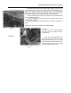
——Heat the small end of connecting rod to 230°—400℃,
and apply SAE50 engine oil or graphite colloid oil on the outer
circumference of the piston pin hole. Then press the piston pin
into the hole of connecting rod small end and piston pin. One
end of the piston pin may be 0.7mm mostly out of the pin hole
or 0.3mm mostly in the seat. And plug the other end of it into
the pin seat.
The piston head means the front arrow. The outer end
of piston pin means the front lug, which should has a
same direction with “F” near the large end of the
connecting rod.(with ‘480’ mark on some blanks and
the mark side forward.)
——After the piston, piston pin, and the connecting rod are put
together, print and sculpture the cylinder numbers with the
3mm words on the top of piston, the connecting rod and the left
side of rod cap (viewed from the front). Be sure not to be
deformed on the connecting side during printing.
——The dimension of piston ring.
478 piston ring 480 piston ring
Paint marker (group) Size of
gauge
Paint marker
(group)
Size of
gauge
Yellow paint +no paint
(standard)
77.22 No paint
(standard)
79.94
Yellow paint+ purple
paint (oversize 0.29)
77.51 Purple paint
(oversize 0.29)
80.23
Yellow paint +blue
paint (oversize 0.5)
77.72 Blue paint
(oversize 0.5)
80.44
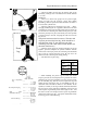
——When installing the piston ring, the mark side should
be put up and the second compression ring outside cut section
should be put down and remember not to the contrary. Firstly
the oil controlling ring, then the second compression ring, and
finally the first compression ring. As assembling the ring, its
maximum tension should be inferior to the diameter of the
cylinder(+1. 65mm), or the ring would be deformed and broken.
The two cotters of the steel band combination oil ring and oil
control spacer ring should be parted with a angle of 120°.And
the cotters of cast iron oil ring and screw spacer ring should be
parted with a interval of 180°. The piston should rotate freely
in the ring groove without blocking.
Fig.53
Fig.54
Fig.55
Front
lug
No.1 compressing
ring
No.2 compressing ring
Steel band
combination oil ring
Cost iron oil ring
Only one side