
Manual


Engine Maintenance And Servicing Manual
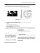
Timing:
Rotate the engine pulley (2) to keep cylinder 1 and cylinder 4 at TDC, i.e. the mark on the pulley (2) and
the mark (3 and 4) on the timing wheel cover of engine must be matched (see figure. 145).
Speed/ TDC sensor
Check if the sensor is located in the twentieth tooth after the breach in the flywheel signal panel
1— Speed/ TDC sensor (crankshaft position sensor)
2— Pulley
3— TDC reference point on the pulley
4— TDC reference point on the timing gear cover
5— synchronous tooth
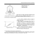
Check the air gap between the sensor and flywheel:
Magnetic thickness gauge is used for checking the air gap between the sensor and flywheel. Measurement
should be made at least at three different teeth with a equal interval of 120°. The value should be 2±0.6mm.
A. Speed sensor signal
B.ECU power signal
C. Current circle for primary coil circuit
a. Ignition advance angle relative to cylinder 1
TDC
4.3 absolute pressure sensor
The sensing element of absolute pressure sensor is printed
in a ceramic membrane by the wheatstone bridge silk PCB.
One side of the membrane is absolute reference vacuum and
the other side is actual vacuum of the intake manifold. The
signal (piezoresistance type) produced by the distortion of
ceramic membrane which is installed in the bracket is
magnified by the circuit located in the carrier before being
transferred to ECU.
See from the front end, rotation direction
Top dead center position
Crankshaft
position sensor
Fig. 145 sensor position and timing
reference point
Fig. 146 Magnetic sensor output signal wave
PDF 文件使用 "pdfFactory Pro" 试用版本创建 www.fineprint.com.cn