
LUBRICATION SYSTEM


ENGINE LUBRICATION SYSTEM
DESCRIPTION OF LUBRICATION SYSTEM
——
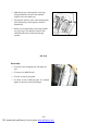
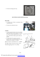
The rotor oil pump (1) at the front end of the
crankshaft sucks oil out of the oi
l pan (3) by
oil strainer (2) and pressurizes oil, and then
the pressurized oil will enter the full-
flow oil
filter through the auxiliary
oil passage (4) at
the left side of the cylinder(view from the
front). A relief valve (6) is set up inside the oil
pum
p to control the pressure at the main oil
passage. The relief valve opens at
440kpa+20kpa, and the filtered oil flow from
the center hole in oil filter through the center
hole of the filter terminal to the engine main
oil passage.
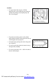
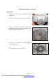
——The main oil passage lubricate the main
bearing through holes on the cylinder block
and lubricate the connecting-rod bearing
through the oil passage inside the crank shaft.
——On the side of the vent pipe of the
connecting-rod bearing is a small oil hole
from where oil will eject to lubricate piston
pin and cylinder.
——
Oil pressure sensor (8) is close to oil filter,
connected to the main passage through an
internal oil passage. And engine oil will be
provided upward to the third camshaft journal
from the upper oil passage.
——Other camshaft journals get oil from the
middle passage of the camshaft, whose ends
are sealed with steel balls.
1. Oil Pump Rotor Assembly
2. Oil Strainer
3. Oil Pan
4. Cylinder Auxiliary Oil Passage
5. Cylinder Main Oil Passage
6. Oil Pump Relief Valve
7. Oil Filter
8. Oil Pressure Sensor
9. Camshaft
10. Hydraulic Jib
B-2
PDF created with pdfFactory Pro trial version www.pdffactory.com