FUEL AND EMISSION CONTROL SYSTEMS INTAKE-AIR SYSTEM … … … … … … … … … … … … … … … … … … … … …D-2 INTEGRAL INTAKE MANIFOLDS … … … … … … … … … … … … … … … …D-2 THROTTLE BODY … … … … … … … … … … … … … … … … … … … … … … …D-2 IDLE SPEED STEP MOTOR … … … … … … … … … … … … … … … … … … … …D-3 THROTTLE POSITION SENSOR … … … … … … … … … … … … … … … … …D-5 INTEGRAL AIR PRESSURE/TEMPERATURE SENSOR… … … … … … …D-6 ASEEMBLY AND DISASSEMBLY OF INTAKE SYSTEM… … … … … … …D-7 CANISTER SOLENOID AND INTAKE/EXHAUST PIPE… … … …
INTAKE-AIR SYSTEM INTEGRAL INTAKE MANIFOLDS Warning: ·When the engine and intake-air system are hot, they can badly burn. Turn off the engine and wait until they are cool before removing the intake-air system. ·Fuel vapor is hazardous. It can easily ignite, causing serious injury and damage. Always keep sparks and flames away from fuel. ·Fuel line spills and leakage are dangerous. Fuel can ignite and cause serious injuries or death and damage. Fuel can also irritate skin and eyes.
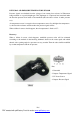
To avoid the mixture condensing and freezing in certain condition, throttle valve adjuster is supported by anti-deadlock screw to prevent it from completely closing, and heated by circulating coolant. Idling speed step motor (4) and throttle position sensor (5) are installed on throttle body. 1.Throttle Cable Supporter 2.Anti-deadlock Screw 3.Throttle Valve Opening Angle Control 4.Idling Speed Step Motor 5.
1.Idling Speed Step Motor 5. Throttle Body 2. By-pass Hose 3. Lock Pin 6. ECU Electrical Control Unit Qo. Air Leakage Volume Of Throttle Q. By-pass Air Volume Of Step Motor 4. Throttle Valve 7.Steel Lock Ring Specification: The coil resistance is R=53 ± 10Ω at 20℃. A max air intake volume will be got when the lock pin turns back 200 steps (approx 8mm stroke, correspond to about 60kg/h air intake volume).
THROTTLE POSITION SENSOR The sensor, including a potentiometer, the movable part of which is controlled by the throttle axis. ECU supplies a voltage approx. 5V to the potentiometer when working. From idling to throttle full open, oil injection process is administrated by parameters gained from throttle valve opening angle. ECU identifies whether the throttle is in the open or close position according to the output voltage and modifies the mixture ratio.
INTEGRAL AIR PRESSURE/TEMPERATURE SENSOR Pressure signals are obtained from the voltage of one among four resistors in Wheatstone bridge marked on a special diaphragm. This diaphragm is compressed and stretched under the absolute pressure from inside of the manifolds (thus the above resistor is under pressure too). Air temperature sensor is a negative factor temperature sensor. So the higher the temperature is, the lower the resistance and the weaker the pressure signals will be.
ASEEMBLY AND DISASSEMBLY OF INTAKE SYSTEM Remove accessories around the engine: 1.Loosen fastening clamp, demount air cleaner and air intake hose. 2.Remove throttle cable and clutch cable. 3.Remove all intake pipes and vacuum hoses around engine. 4.Put down water hose to discharge anti-freeze liquid. 5.Disassemble the throttle position sensor/ canister solenoid/crankshaft position sensor/Injection nozzle / knock sensor and wire plugs on electric components like fuel pressure switch.
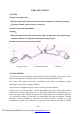
OIL-VAPOR SEPARATOR A 2 1 B E C D 1.Oil-vapor separator 2. Air cleaner 3.Others---ventilating pipe in crankcase Working principle: Main function of the oil-vapor separator is leading gas in crankcase to intake manifolds through oil-vapor separator, which keeps pressure in crankcase within a certain range and prevent gas in crankcase from mixing and flowing out.
EXHAUST SYSTEM OUTLINE Exhaust system inspection : ·Start the engine and inspect each exhaust system component for exhaust gas leakage. ·If leakage is found, repair or replace as necessary. Exhaust system removal/installation Warning: ·When the engine and exhaust system are hot, they can badly burn. Turn off the engine and wait until they are cool before removing the exhaust system. Exhaust assembly and oxygen sensor position 1. Oxygen Sensor 2. Catalytic Converter 3. Silencer OXYGEN SENSOR To gain max.
the mixture concentration value in time and change mixture thicker or thinner to make it always be close to chemical reaction equivalence ratio. The voltage range of which is 0.980~1.020V. To reach working temperature rapidly (~300°C), a resistor (4) installed in the sensor can shorten the starting electric time of the porcelain. It means sensor can be installed in cold area of exhaust hose.
Exhaust gas emission CO% HC (p.p.m.) CO2 (%) Before catalytic converter 0.4 - 1 < 600 > 12 After catalytic converter < 0.35 < 90 > 13 See the above table, using three-way catalyst converter can reduce three types of harmful gases in exhaust gas at the same time: HC, CO, NOx, while harmless CO2 increases. The following factors will rapidly damage the catalytic converter: ——Fuel contained lead, which will decrease converter efficiency even invalidate catalytic converter.
——Install Oxygen sensor assembly on front hose assembly with a tightening torque of 45±4.5Nm. ——Install 3 M10 double head studs on exhaust manifolds. ——Lay exhaust hose pad, install front hose assembly on exhaust manifolds. ——Mount 3 M10 copper nuts with a tightening torque of 60±3Nm.
Note: ·Eccentricity between front silencer and the intake/exhaust hose is 18mm. Adjust front silencer position in assembly to guarantee a gap between the front silencer and the channel heat insulator more than 10mm. ·In assembly, hose clamp should not be aslant installed around the exhaust hose. ·Distance between the expanding section on exhaust hose and the section of hose clamp should be 1~4mm in assembly. ⑦ Installation of exhaust hose bracket: ——Install exhaust hose bracket.
FUEL SYSTEM ASSEMBLY AND DISASSEMBLY OF FUEL SYSTEM Before repair procedure Warning: ·Fuel vapor is hazardous. It can easily ignite, causing serious injury and damage. Always keep sparks and flames away from fuel. ·Fuel line spills and leakage are dangerous. Fuel can ignite and cause serious injuries or death and damage. Fuel can also irritate skin and eyes. To prevent this, always complete the following “Fuel Line Safety Procedure”.
Caution: ·Connecting the wrong check connector terminal may possibly cause malfunction. Carefully connect the specified terminal only. 1.Short the check connector terminal F/P body GND using a jumper wire. 2.Turn the ignition switch to ON position to operate the fuel pump. 3.Pressurize the system in this way for at least 5minites to be sure of no leakage. ·If there is fuel leakage, inspect the fuel hose, hose clamps, and fuel pipe sealing surface, and replace as necessary.
Installation of fuel case assembly: ——Install fuel tank assembly. ——Install 2 tapping screws (M6) on fuel tank mouth. ——Set up 3 fuel tank fixed belts and 5 M8 bolts. ——Tighten 5 M8 bolts (tightening torque is 30± 3Nm) and 2 tapping screws (tightening torque is 4±0.5Nm). ——Install fuel mouth cap and steel wire stopper. ——Connect import and export tube on fuel tank, clamp tube lock hoop by special tool.
Installation of fuel filter: ——Set up fuel filter assembly in fuel filter protection box assembly. ——Connect import and export tube in both end of fuel filter, clamp tube lock hoop by special tool. ——Using two M8 lock nuts to install protection box assembly under vehicle ground board. Tighten bolts, and the tightening torque is 30 ±3Nm. Installation of fuel tube: ——Set up lock clamp on relevant screw under vehicle body. ——Cover protective sleeves, set up fuel tube on relevant lock clamp.
counter-clockwise, slowly bring forward fuel pump assembly. ——Pull out fuel level sensor with little upwards strength. Installation of accelerator cable: ——Install rubber jacket on vehicle front boarding. ——Thread accelerator cable through rubber jacket, then push it to right position. ——Install hook of accelerator cable in gluey block of accelerator pedal. ——Install the other end of accelerator cable on throttle valve rocker of throttle valve body.
OPERATION CONTROL OF ENGINE FUEL SUPPLY SYSTEM 1. Start engine: In start process, ECU firstly inject to all cylinder at the same time to shorten start time. After that, ECU will inject according to phase order. 2.
5. Full load: In full load status (distinguished from throttle potentiometer and absolute pressure sensor), ECU obtains maximal output power by increase basic fuel injection time, while temperature of catalysis converter is kept in prescriptive range. 6. Air pressure modification: Air pressure will change with different altitude, which will cause change to volumetric efficiency. That is why basic specified parameter (fuel injection time and by pass air input) need to be modified.
10. Electric power balance: Normal working of electric components (front light, heat back window, etc.) will make battery voltage lower than 12.2V, electric components power demanded in that time is larger than electric power from generator. That is to say, negative “electric power balance” may cause damage to battery. In that condition, ECU accelerates idle speed step by step (from 800 r/m to 1200 r/m) to make adequate electric power from generator.
Working pressure: 350kpa Working temperature: -30℃~+110℃ 6.Turn the ignition switch to LOCK position and disconnect the jumper wire. 7.Complete the “After repair procedure”. Atomization 1.Inspect atomization pattern. ·If the atomization is faulty, replace the fuel injector. Half no scavenge fuel supply integrated module Fuel supply module is in fuel tank, which includes: - Fuel pump; - Diaphragm type fuel pressure adjuster; - Fuel filter (out of the fuel tank) 1.Fuel Supply Module 6.Cone Way Valve 2.
Fuel pump Fuel pump inspection Note ·When ignition switch is at ON position, it is normal to hear the sound of fuel pump running. Fuel pump is located in fuel tank, and there is netlike filter in the fuel pump entrance. Internal gear positive displacement fuel pump should use unleaded gasoline. Rotor is driven by motor, while motor power comes from battery through relay. There is safety valve installed in fuel pump.
Fuel Pump Hold Pressure Inspection Warning ·Fuel line spills and leakage are dangerous. Fuel can ignite and cause serious injuries or death and damage. Always carry out the following procedure with the engine stopped. Caution · Disconnecting/connecting the quick release connector without cleaning it may possibly cause damage to the fuel pipe and quick release connector.
1.Fuel Rail 2.Fuel Injector 3.Fuel Feeding Port Fuel injector This system adopts head supplying single hole Fuel injector, and fuel injection pressure is 3.5bar. Fuel injected from fuel injector keeps in atomization and comes into cone angle (15 degree to injection nozzle axis). Control logic of Fuel injector is “phase, order” controlling. These four fuel injectors are controlled by air input order of four cylinders. Fuel injector is open on expansion stroke till intake stroke started.
Specification: Voltage: 12V Resistance: 13.8 ~ 15.2Ω± 10%( on 23°C) Remark: Force on fuel injector socket in assembly and disassembly must be less than 120N, or it will influence function. Caution ·use of a deformed injector retaining clip will cause the injector to not engage correctly. Always use a new clip when reattaching the injector, otherwise it may cause the injector to rotate. D-26 PDF created with pdfFactory Pro trial version www.pdffactory.