
Service Manual


152
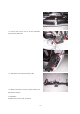
Section 6 Evaporator Harness
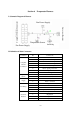
I. Schematic Diagram of Harness
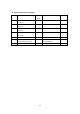
II. Definition of Main Connectors
Connector Pin Connect To
1 Fan motor + terminal
2 Fan position switch HI position
3 Governor resistor ML position
4 Governor resistor MH position
5 Governor resistor LO position
6 Sensor signal ground wire
7 Power ground wire
Complete
Vehicle
Connector
8 Sensor signal
1 ECU(17) Temperature
Sensor,
2 ECU(22)
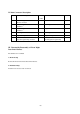
1 Motor – terminal Fan Power
Supply
2 Motor + terminal
1 Power ground wire
2 Fan motor + terminal
3 Fan motor - terminal
Fan Relay
4 Fan position switch HI position
1 LO position
2 HI position
3 M1 position
Governor
Resistor
4 M2 position
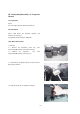
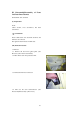
Fan Power Supply
Fan Relay
Temperature Sensor
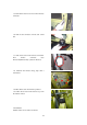
Governor Resistor
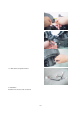
Fan Power Supply
Complete Vehicle Connector