Service Manual for Chery QQ6 (Electrical, Circuit) After Sales Service Department of Chery Automobile Sales Co.
TABLES OF CONTENTS Chapter One Control Principle of Some Systems ..................................................................4 I. Control Principle of Starting System.....................................................................................4 1. Starting System .............................................................................................................4 2. Charging System.........................................................................................................
. Engine’s Anti-Theft System ........................................................................................28 4. A/C and Defrost Systems ............................................................................................29 5. Horn, Backup Lamp, Cigaretter Lighter, Ceiling Lamp and Luggage Boot Light .....30 6. Radio...........................................................................................................................31 7. Front/Rear Wiper .............................
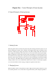
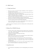
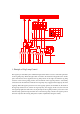
Chapter One Control Principle of Some Systems I. Control Principle of Starting System 30 3 0a 15 15 a Ka Ignition Swit ch Ignit ion Swi tch To Fuse F17 B attery Gen erator S tarter At Body At Transmissi on 1. Starting System When the ignition switch is turned to ST position, the pull-in winding of the starter powers on, and then the starting gear of stater motor is pushed to and engaged with the gear of flywheel.
operating. When the generator itself can generate electric power, the system will switch to the self-excitation mode. In addition, when the generator is generating electric power, it gives a signal to the relevant instrument via the D+ terminal. After the instrument receive the signal from the generator, the battery indicator on the instrument will be extinguished. 3. Troubleshooting and Elimination 3.1.
II. BCM Control 1. Ceiling Lamp Control l l l l l l When any door opens, the ceiling lamp lights automatically, and then extighuishes 15 minutes later after the door opens. The ignition switch is placed to OFF position, and, 8s later after all four doors close, the ceiling lamp gradually extinguishes, with duration of 2s. During the ceiling lamp delays 8s, if the ignition switch changes OFF position to ON position, the ceiling lamp extinguishes immediately.
l l The door lock and window glass regulator can’t act at the same time, and the former is preferred if conflict. Automatic door lock control (pre-reserved signal, suitable for the speed locking of vehicle equipped with air bag and the unlocking after the air bag explodes). 4. Anti-theft Alarm System 4.1. Door lock remote control function When the remote control key’s UNLOCK/LOCK pushbutton is pressed down, the door lock motor will act 0.6 s ± 50 ms.
arming indicator light continuously flashes; ③ if the ceiling lamp switch is in the controlled position and the ceiling lamp is in OPEN position, the ceiling lamp closes. 4.4. Disarm mode: a) How to disarm: Condition: The body is in the normal arming mode. Operation: Press down the “UNLOCK” button on the remote controller.
without the alarm horn). 4.6. Disalarm mode a) How to disalarm: After the body enters into the alarm mode: ① press down any pushbutton on the remote controller. b) Body state after disalarming: 1. If the triggered alarm door is in open state (not give an alarm for the vehicle without the alarm horn). Press down the UNLOCK pushbutton on the remote controller to ① disalarm; ② unlock the central door lock.
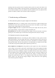
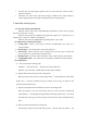
30 30a 15 15a Ka Clearance Lamp Power Power Headlamp OFF Clearance Lamp Headlamp Terminal Light Control Switch Rear Right Tail Lamp Right Clearance Lamp License Plate Lamp Front Right Fog Lamp Front Left Fog Lamp Rear Right Fog Lamp Rear Left Fog Lamp Rear Left Tail Lamp Front Fog Lamp To Instrument Left Clearance Lamp Rear Fog Lamp Relay Front Fog Lamp Relay To Instrument To Each Night Light Switch 1.
2. Principle of Clearance Lamp Control The clearance lamp is controlled using a light switch. When the switch is in the clearance lamp position, the terminals 5# and 6# of the light switch will be turned on to make the power supply from the fuse F4 get to the clearance lamp via the angle 5#, and the front and rear clearance lamps connect to the fuses F13 and F14 respectively. In addition, the license plate lamp also lights. 3.
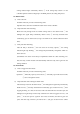
30 30a 15 15a Ka Light Switch Clearance Lamp Power Power Headlamp OFF Clearance Lamp Headlamp Terminal Light Control Lamp High Beam Relay Low Beam Relay High Beam Indicator Right High Beam Right Low Beam Left High Beam Left Low Beam Light Regulating Switch 1. Principle of low beam lamp control When the light switch is in the headlamp position, the terminal 8# of the light switch offers the light control switch’s 6# terminal the electric power.
3. Principle of the passing lamp control When the light control switch is in PASS position (passing lamp position), the switch directly offers the high beam relay the electric power from the fuse F4, without via the light switch, which lights up the high beam lamp. So, it is unnecessary to open the light switch when the passing lamp is in service. V.
1. Principle of turn signal lamp control The turn signal lamp control is divided into three categories while the final control is implemented by the flasher relay. Alarm switch control: The alarm switch has the power supply from the battery F7 fuse. So, it ensures that the switch can work in case that the ignition switch doesn’t turn on. When the alarm switch is in ON position, the flasher relay is powered by the terminals 5# and 6# of the alarm switch.
1. Control principle The electric rear-view mirrorr is controlled by a switch, without any relay. When the L position is selected, the Nos 2 and 3 circuits form a loop respectively with the internal circuit of the switch. Take the Y1 direction as an example, when pushing the switch in the Y1 direction, the switch connects to the power supply from F19 while the power supply connects with the No 2 circuit (with Nos 2 and 3 circuits when the switch is in L position).
1. Control principle This wiper system’s control is a switch type one while the intermitten control adopts the intermitten relay. The wiper motor is grounded itself. When the switch is in the Low Speed position, the wiper switch is used to connect the power supply from F19 with the No 1 terminal of the wiper motor, and the wiper starts to operate at low speed.
Chapter Two I.
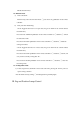
前/室(前仓和室内线束的插件) Compartment /Interior (Compartment and Interior Harness’s Connector) Definition 针脚定义 of ECU Pin Definition针脚定义 of ABS Pin 室/仪 (室内线束和仪表线束的 插件) Interior/Instrument B (Interior Harness and Instrument Harness’s A Connector)
Interior/Instrument A (Interior Harness and Instrument Harness’s A Connector) 室/仪 (室内线束和仪表线束的 插件) 室/左前 (室内线束和左前门线束的 插件) Interior/FL A (Interior Harness and Front Left Door Harness’s A Connector) 室/左前B (Interior (室内线束和左前门线束的 Interior/FL Harness and Front Left Door 插件) Harness’s B Connector) 室 右前(室内线束和左前门线束的插件) Interior/FR A (Interior Harness and Front Right Door Harness’s Connector) 室/左后 A(室内线束和左后门线束的 Interior/RL (Interior Harness and Rear Left Door插件) Harness’s A Connector)
室/左后 B(室内线束和左后门线束的 Interior/RL (Interior Harness and Rear Left插件) Door Harness’s B Connector) Interior/RR Harness and Rear Right Door Harness’s 室/右后B (Interior (室内线束和右后门线束的 插件) B Connector) Interior/RR A (Interior Harness and Rear Right Door Harness’s A Connector) 室/右后 (室内线束和右后门线束的 插件) 室/后(室内线束和后背门线束的插件) Interior/B (Interior Harness and Back Door Harness’s Connector) BCMA (BCMA Connector Pin Definition) ( 插头阵脚定义)
BCMB (BCMB Connector Pin Definition) ( II. 插头阵脚定义) Drawing Description 1. Main Symbol Description Symbol Meaning Symbol Meaning Circuit Connection Motor Fuse Position and SPecification Bulb Relay ON/OFF Control Shielded Wire Resistor Element Shielded Wire Solenoid This section is not involved in this system LED Connector Ground Remark: Please refer to circuit and real object to confirm another symbols. 2.
31– (GROUND): ground cable, from the negative electrode of the battery Wire diameter and color: 3. Definition of Main Controller In this schematic diagram of circuit control, “CE/” means the instrument electrical box integrated with relay connector; In this schematic diagram of circuit control, “ECU” means the engine control computer; In this schematic diagram of circuit control, “BCM” means body control computer. 4.
Grounding point of interior harness under the left A post. Grounding point of interior harness at the left side of luggage boot. Grounding point Grounding point of interior harness at the inside of rear right fender. of defroster harness at the top of back door.
III. Schematic Diagram of Main Electric Box and Module Position Engine Compartment Electrical Box At the right side of engine (viewing it from the front to back) Engine’s ECU Instrument Electrical Box OBD Diagnostic Interface At the driver side, and located at the clutch pedal. Body Control Module (BCM) is located under the driver’s seat.
IV. Electrical Box Description 1. Instrument Electrical Box ABS (15A) O2 SENSOR(2) (10A) ILL.RH (20A) C/FAN(LO) ILL.
V. Schematic Diagrams of Circuit Control 1.
2.
3.
4.
5.
6.
7.
8.
9.
10.
11.
12.