Service Manual for Chery QQ6 (SQR473F Engine-Mechanical) After Sales Service Department of Chery Automobile Sales Co.
CONTENTS Chapter One Introduction of Characteristics .................................... 4 I. Overview ...............................................................................................................................4 II. Number Position of the Engine ............................................................................................4 III. Connotation of Engine Number ..........................................................................................
IV. Adjustment of Timing (minor overhaul) ...........................................................................30 Chapter Nine Disassembly of Engine Assembly ............................ 31 I. Disassembly Procedure........................................................................................................31 II. Installation Procedure.........................................................................................................39 Chapter Ten Disassembly of Intake Manifold ......
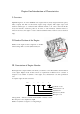
Chapter One Introduction of Characteristics I. Overview SQR473F engine is one of the ACTECO series engines that are jointly designed and developed by Chery company and AVL-a world famous engine design company. This engine adopts such advanced technologies as overhead double camshaft structure, 4 air valves, electronic throttle body and electronic accelerator pedal etc.
The bore refers to diameter of cylinder sleeve, which is specified by a 2-3 digit integer with the decimal part rounded and millimeter as unit. Characteristic code: indicates the most basic characteristics of an engine and is specified by 1 digit upper case English letter. Specification code: specified by 1 digit upper case English letter, which is used as an additional distinguish code when distinguish is required in case structure, principal parameter or oil supply mode etc.
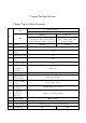
Chapter Two Specification I. Engine Type and Major Parameters Basic Parameters Item No. Type SQR473 SQR473H SQR473F Vertical type, 4 cylinder, water cooling, 4 Vertical type, 4 cylinder, water stroke, in-line double overhead camshaft, cooling, 4 stroke, in-line double controlled burn rate, variable valve timing overhead camshaft SQR473F 1 Model SQR473H 2 Fuel Supply Mode Multi point electric control gasoline injection 3 4 5 6 Cylinder Diameter 73.0 (mm) Piston Stroke (mm) 77.
Crank Angle with Intake Valve Opening as 1mm 400 369 610 569 200 140 390 350 12±5 12±5 (°) Crank Angle at 1mm before Intake Valve Closing (°) 17 Crank Angle with Exhaust Valve Opening as 1mm (°) Crank Angle at 1mm before Exhaust Valve Closing (°) 18 Ignition Advance Angle (°CA) Cylinder 19 Compression 1.00~1.35 Pressure (MPa) (200~300r/min) 20 21 Overall Dimension 613×507×734 (length×width×height) Electronic fuel UAES injection system II. Major Maintenance Parameters of Engine No.
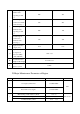
No. Name Dimension and tolerance Thickness of connecting rod big end 220-0.1 Width of crankshaft connecting rod journal 22+0.30+0.15 First piston ring groove height 1.2+0.05+0.03 4 5 Top compression ring height Second compression ring height 1.5-0.005-0.030 piston oil ring groove height 2.5+0.03+0.01 Blade height of steel strip composite type oil ring 0.46±0.02 ring 0.035~0.08 -0.03 1.5+0.04+0.02 Bracing spring height of steel strip composite type oil 0.15~0.4 -0.
No. Name Diameter of cylinder head third bearing hole Diameter of camshaft fourth journal 18 Diameter of cylinder head fourth bearing hole Diameter of camshaft fifth journal 19 Diameter of cylinder head fifth bearing hole 20 Camshaft thrust groove width Outside diameter of camshaft oil seal 21 Diameter of cylinder head oil seal hole Diameter of cylinder head jib hole 22 Dimension and tolerance ( φ 24e6( φ 24 H 7( φ 24e6( φ 24 H 7( 30.65 H 7( −0.040 −0.053 +0.021 0 −0.040 −0.053 +0.021 0 +0.
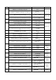
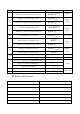
guide Fit clearance between exhaust valve stem and valve guide 0.032~0.063mm Fit clearance between hydraulic jib and cylinder head hole 0.006~0.035mm IV. Engine Primary Tightening Torque Table Number Multiple steps tightening (torque + Tightening of bolts/ Bolt No.
Number Multiple steps tightening (torque + Tightening of bolts/ Bolt No. Connection part Part name angle) torque gaskets (thread specification) Nm (primary (piece) tightening) First step Second step Third step tightening angle (°) angle (°) —— —— torque (Nm) Phaser control valve-first Inner hexagonal bolt M6×1×15 2 8+3 —— Cylinder head-cylinder block Inner hexagonal bolt M10×1.
Number Multiple steps tightening (torque + Tightening of bolts/ Bolt No.
Number Multiple steps tightening (torque + Tightening of bolts/ Bolt No. Connection part Part name angle) torque gaskets (thread specification) Nm (primary (piece) tightening) First step Second step Third step tightening angle (°) angle (°) torque (Nm) 64 Exhaust manifold-cylinder head Stud bolt M8×1×46 9 12+3 —— —— —— 65 Exhaust manifold-cylinder head Hexagon nut M8 9 20+5 —— —— —— Hexagon bolt M8×12 3 20+5 —— —— —— Hexagon bolt M8×20 1 20+5 —— —— —— M14×1.
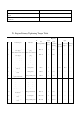
3 Connecting rod bearing shell and connecting rod journal SJ10W-40 4 Cylinder sleeve hole SJ10W-40 5 Main bearing lining and crankshaft main journal SJ10W-40 6 Crankshaft thrust sheet (at oil groove side) and thrust surface SJ10W-40 7 Head and thread of connecting rod bolt SJ10W-40 8 Head and root of main bearing cap bolt SJ10W-40 9 Rear oil seal edge and crankshaft oil seal journal SJ10W-40 10 Head and root of cylinder head bolt SJ10W-40 11 Valve guide orifice SJ10W-40 12 Valve
VI. The Parts where Rubber Coating are Required during Assembly of Engine No.
Chapter Three Special Tools Please use the special tools that we designated to perform maintenance, otherwise it will cause accident or damage the machine. I.
production of this tool to other manufacturer. This tool is of the first modification. HAZET-6290-1CT means it is a standard tool produced by HAZET company with its model as 6290-1CT. II. Special Tools Chart CH-20002 CH-20003 Installation tool for camshaft oil seal: used to install camshaft oil seal. Same as A5 Engine timing tool: used to time crankshaft. Same as A5 CH-20004 Adaptor: used to install and remove valve spring (match with Eastar special tool MLR-MD998772A).
CH-20008 Installation sleeve for crankshaft front oil seal Same as A5 CH-20009 Locating tool for flywheel: used to locate flywheel. Same as A5 CH-20010 Camshaft timing tool: used to time camshaft. Same as A5 CH-20011 Installation tool for camshaft oil seal: used to install camshaft oil seal. Same as A5 CH-20012 Valve oil seal guide sleeve: used to install valve oil seal. Same as A5 CH-20013 Valve oil seal remover: used to remove valve oil seal.
CH-20017 Installation tool for valve keeper: used to install valve keeper. Same as A5 CH-20018-A Valve spring remover: used to remove valve spring. Same as A5 Recommended tools Loop wheel machine: used to raise engine. Engine maintenance workbench: the workbench for disassembly and assembly of engine. Fuel pressure gauge: used to measure oil pressure of engine.
Pressure gauge for cylinder: used to measure cylinder pressure. When measuring, remove spark plug first, screw instrument pipe orifice into the position of spark plug, use starter to drag the engine to rotate, and then fetch the maximum reading of the pressure gauge for cylinder as cylinder pressure of this cylinder. Chapter Four Measurement of Cylinder Pressure I.
1.3 Screw the cylinder pressure gauge joint slowly and vertically into the spark plug hole. Do not screw too tightly for fear that it may be difficult to disassemble. 1.4 Step down clutch pedal, start the engine and let it run for about 5-6s, then fetch the numerical value. 2. Judgment of cylinder pressure value 2.1 Correct cylinder pressure The standard cylinder pressure value should be 10-13.5bar.
Chapter Five Disassembly of Power-assisted Steering System I. Disassembly Procedure 1. Use a snap ring pliers to loosen the clamp on connecting hose of steering fluid reservoir and steering pump. Use a clean container to reclaim the steering fluid. 2. Use a 21# sleeve to remove the fixing bolt of steering pump oil pipe. Torque: 20+5Nm. 3. Use a 10# sleeve to loosen the (upper) fixing bolt of steering pump adjusting bracket. Torque: 20+5Nm. 4.
5. Use a 10# open end wrench to loosen the adjusting bolt of steering pump bracket, and then pull the steering pump upwards to loosen and take off the belt. 6. Use a 10# sleeve to loosen the connecting bolt of steering pump and compressor bracket, pull out harness connector, and then dismount the steering pump assembly. Note: when dismounting the steering pump, please block the oil pipe joint with clean cotton cloth. II.
Chapter Six Disassembly of A/C Compressor I. Disassembly Procedure Before disassembling the compressor, disassemble the steering oil pump first. 1. Use a 12# sleeve and a universal joint connecting rod to loosen the connecting bolt of A/C high and low pressure pipelines. (Note: if there is R134a in the condenser, use a special equipment to reclaim first.
II. Overhaul of Compressor Inside of the compressor are assembled with highly machined fine parts, in case abnormal noise or internal failure is found, replace the assembly. III. Installation procedure For the installation order, please refer to the disassembly order, and then follow the order adverse to that for disassembly to install.
3. Use a 13# sleeve to remove lower fixing bolt of the generator. Torque: 40+5Nm. 4. Use a 10# sleeve to remove the fixing bolt of generator anode harness, pull out the harness connector, remove the belt and then take out the generator. II. Overhaul of Generator In case the generator makes abnormal noise or its yield is too high or too low, replace the assembly. III. Installation Procedure The installation order of the generator is adverse to that for its disassembly.
Chapter Eight Replacement of Engine Timing Belt I. Disassembly Procedure In order to ensure normal and highly effective working of the engine, replacing the timing belt at 50,000km mileage is recommended. 1. Disassembly of engine timing belt: 1.1 Follow the disassembly methods for power-assisted steering pump, compressor and generator to disassemble the generator and compressor belt. 1.2 Use a 5mm hexagon wrench to remove the five fixing bolts on timing upper cover. 1.
1.5 Insert the special tool CH-20003 into the timing hole and tighten, use a wrench to turn the big nut in the crankshaft pulley to make the crankshaft rotate, at the same time, slowly screw in CH-20003 until the crankshaft can not rotate back and forth any longer. 1.6 Use a 13# sleeve to remove the six fixing bolts of crankshaft pulley and take out the crankshaft pulley. Torque: 55+5 Nm. 1.7 Use a 10# sleeve to remove the six fixing bolts on timing lower cover. 1.
1.10 Use a 10# sleeve to loosen the fixing bolt of the tension pulley to take off the timing belt. Torque: 27±3 Nm. Note: when taking off the timing belt, pay attention to running direction of the belt and refer to running direction of the engine crankshaft and the arrowhead direction on the belt. II. Installation of Timing Belt 1. Loosen the fixing bolt of tension pulley and turn the tension pulley to minimum tension position. 2. Install the belt. 3.
III. Adjustment of Timing (general overhaul) 1. Turn the crankshaft to make the four pistons align on a horizontal line in the cylinders, screw the special tool into the crankshaft timing adjusting hole at left rear of the cylinder (last segment of the crankshaft), and then make the crankshaft unable to turn left and right (the bolt of the special tool must enter into the screw hole plane of the cylinder). 2.
Chapter Nine Disassembly of Engine Assembly I. Disassembly Procedure Note: Please use regular equipment, especially for such equipment as crane etc., so as to avoid occurrence of accident. Before any disassembly job, disassemble cathode of battery first, so as to protect safety of electricity consumption equipment. When disassembling engine suspension, pay attention to disassembly order, so as to avoid occurrence of accident. 1. Disassembly of engine wire harness 1.
3. Use a 13# sleeve to remove the bolt of battery support fixed mount. 4. Disassembly of cooling system. 4.1 Hoist the vehicle, place away a coolant collector, unscrew bleeder bolt of the water tank to discharge the coolant. 4.2 Use the snap ring pliers to loosen the clamp on connecting pipe of water tank. 4.3 Use the snap ring pliers to loosen the connecting water pipe of A/C heating water tank. 4.4 Use the snap ring pliers to loosen other connecting water pipes. 5.
5.3 Use a 10mm sleeve to remove the fixing bolt of discharging tube of water pump and then pull out the discharging tube. Note: in case the O-ring on discharging tube of water pump is loose, broken or aging, be sure to replace. 5.4 Use a 10mm sleeve to remove the fixing bolt of water pump and then take out the water pump assembly; when removing, be careful not to damage cushion of the water pump, if damaged, replace with a new one. The water pump can not be decomposed to maintain. 5.
6. Inspection of thermostat: (1) Under normal temperature, inspect seating status of the valve and it should tightly seat. (2) Inspect opening temperature and maximum stroke of the valve. Opening temperature of the valve is 87±2℃ Maximum stroke of the valve is 8mm Full opening temperature of the valve is 104℃ (3) Then check if the valve closes at the temperature 5℃ lower than the opening temperature. If not compliant, replacement with a new thermostat is required.
9.3 Use a 13# sleeve to remove the connecting bolt of three-way catalytic converter and exhaust intermediate pipe. Torque: 60±5 Nm. 9.4 Use a 10# sleeve to remove heat insulating mattress of exhaust pipe. 9.5 Use a 13# sleeve to remove the connecting bolt of exhaust manifold and three-way catalytic converter. Torque: 60±5 Nm. 9.6 Use a 13# sleeve to remove the fixing bolt of exhaust manifold. 10. Disassembly of connecting portion of transmission case. 10.
10.2 Use pliers to remove the fixing clip of gearshift control cable outer case and then take off the gearshift control cable. 10.3 Use a 13# sleeve to loosen the adjusting screw of clutch control cable and then take off the clutch control cable. 10.4 Use a 13# sleeve to loosen the fixing bolt of clutch control cable on the transmission case. 10.5 Use a 17# wrench to loosen the bleeding bolt of transmission case to discharge the gear oil. 10.
11.2 Use a 18# sleeve to loosen the fixing bolt for front engine mount bracket. Torque: 80±5 Nm. 11.3 Use a crane to hoist the engine until the iron chain just bears tensile force. 11.4 Use a 15# sleeve to loosen the fixing bolt for right engine mount bracket. (at rear of transmission) Torque: 100±5 Nm. 11.5 Use a 13# sleeve to loosen the three connecting bolts for right engine mount bracket. Torque: 65±5Nm. 11.6 Use a 13# sleeve to loosen the three connecting bolts for left engine mount bracket. 11.
12. Separation of transmission case assembly and engine 12.1 Use a 10# sleeve to remove the gearshift control cable bracket on the transmission case. 12.2 Use a 13# sleeve to loosen the four fixing bolts for front engine mount bracket. Torque: 65±5Nm. 12.3 Use a 13# sleeve to remove the connecting bolt of transmission case and engine, and then make the engine and the transmission separate. Torque: 100±10 Nm.
II. Installation Procedure 1. Please follow the order adverse to that for disassembly to install, but care should be taken for the following matters. (1) When hoisting, do not install exhaust manifold first, because the longitudinal separation of engine compartment is not big enough; otherwise, it may affect the assembly. (2) After installation, please adjust the stroke of clutch pedal.
3. Use a 10# sleeve to remove the fixing bolt of compressor bracket. Torque: 30±3 Nm. 4 Use a 10# sleeve to remove the fixing bolt of intake manifold and then take off the intake manifold assembly. Torque: 8+3Nm. Chapter Eleven Disassembly of Cylinder Head I. Disassembly Procedure 1 Use a 10# sleeve to remove the fixing bolt of valve cover. Torque: 8±3 Nm. 2. Get the special tool CH-20010 stuck into the groove on camshaft.
3. Use a 18# sleeve to loosen the fixing bolt of camshaft timing gear. Torque: 120±5Nm. Note: There is no difference between intake camshaft and exhaust camshaft, they can be interchanged. 4. Use a cross-head screwdriver to loosen the fixing bolt on inner fender of timing gear and then take out the inner fender of timing gear. 5. Use a 10# sleeve to remove the fixing bolt of camshaft bearing, take out the camshaft assembly and then the hydraulic tappet system. Torque: 9.5±1.5 Nm.
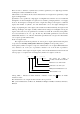
6. Use an hexagon torque wrench to loosen the fixing bolt of cylinder head and then take off the cylinder head assembly. Torque: 50±5 Nm. Note: Follow the order as shown in the figure to loosen the fixing bolts of cylinder head. 7. Disassembly of valve 7.1 Use a special tool to press down the valve spring, take out the locking plate, and then take off valve spring, valve and valve seat insert. 7.2 Use a special tool to pull out the valve oil seal.
II. Overhaul of Cylinder Head System 1. Detection of camshaft 1.1 Measurement of height of cam. Use an outside micrometer to measure wheel height of the cam. Wheel height of the intake camshaft: 37.11mm. Wheel height of the exhaust camshaft: 37.09mm. 1.2 Inspection of camshaft journal. Use an outside micrometer to measure each journal of the camshaft, please see Specification Table for specific data. 2. Detection of valve 2.1 Detection of valve spring. Two items of data of valve spring should be measured.
2.2.2 Measurement of valve guide inside diameter Use an inside micrometer to measure inside diameter of the guide. Note: If abnormal noise is generated due to serious wear of valve guide, do not replace the valve guide, because the assembly technique requirements to valve guide is very strict; please replace the cylinder head assembly. Fit clearance between intake valve stem and valve guide: 0.012~0.043mm Fit clearance between exhaust valve stem and valve guide: 0.032~0.063mm 2.
2.3.4 Detection of planeness of cylinder head Follow the method as shown in the figure to measure planeness of the cylinder head with a feeler gauge; the planeness of the cylinder should not exceed 0.05-0.10mm, if exceeding this valve, replace the cylinder head assembly. III. Assembly of Cylinder Head Assembly 1. Please follow the order adverse to that for disassembly of cylinder head to install, but care should be taken for the following matters during installation. 2.
5. Use a hammer to knock the valve oil seal installation tool, when a metal crash sound is heard, take out CH-20012. 6. The methods for installation and assembly of valve spring are the same. Then install valve, spring, keeper, top barrel and rocker arm. (when installing the top barrel, add a little engine oil into the hole). 7. Install camshaft and camshaft bearing shell cover assembly. Note: When installing, remember to differentiate intake camshaft from exhaust cam.
envelop the oil seal onto the camshaft, and then install use the special tool. 11. Remember to check elasticity of valve cover gasket for aging and breakdown, if any, replace with new one. When installing, pay attention to installation position. 12. Tighten the valve cover bolt.
Chapter Twelve Disassembly and Installation of Oil Pump and Lubrication System I. Disassembly Procedure 1. Roll over the engine and use a 10# sleeve to remove the fixing bolt of oil pan. Torque: 15+3 Nm 2. Use a screwdriver to pry out the oil pan at the given position for prying out on the oil pan. Note: Because the oil pan and cylinder block are sealed with glue, so, do not knock with such hard articles as hammer etc. when disassembling, use a rubber hammer to slowly strike at left and right instead. 3.
5. Use an 8# sleeve to remove the four fixing bolts of oil pump. Torque: 8+3Nm 6. Take off the oil pump assembly and then the oil pump shim. Note: Do not split the oil pump shim forcibly when disassembling for fear to cause leak. 7. Use an hexagon wrench to remove the two connecting bolts of oil pump. 8. Use a screwdriver to pry the crankshaft front oil seal and then take out the oil seal.
II. Overhaul of Oil Pump if it is suspected that engine oil pressure may has problem, disassemble the oil pump and check elastic force of relief valve spring and if the valve is locked. Note: The oil pump is of inner rotor type, which can not be maintained under normal conditions, because its finish size and material ensure its reliability. III. Installation Procedure The installation order is adverse to that for disassembly, but care should be taken for the following matters. 1.
2. Completely and softly shovel off the glue on the surface of oil pan with a flat shovel and then apply new sealant uniformly (see the table above for type of the sealant). Note: As soon as new sealant is applied properly, assemble at once; otherwise, the sealant may freeze, which may affect the sealing effect. Chapter Thirteen Disassembly of Crank-Connecting Rod Mechanism I. Disassembly Procedure 1 Use a 13# sleeve to remove the fixing bolt of clutch cover. Torque: 23±2 Nm 2.
4. Use a 10# sleeve to remove the fixing bolt of crankshaft lower bearing cap and cylinder block. 5. Use a 19# sleeve to remove the fixing bolt of crankshaft main bearing cap. Note: The surface between cylinder block and bearing cap is ensured by high precision machining plane, so, do not use any hard article to scuff this surface. 6. Take off crankshaft rear oil seal assembly, remove bearing shell cover, and then take off crankshaft assembly. II. Overhaul of Crank-Connecting Rod System 1.
1.3 Measurement of main journal clearance: place a plastic feeler gauge on the crankshaft main journal, tighten the main bearing shell cover to specified torque and then loosen it, use the thickness check list on the plastic feeler gauge to read the value. The normal value should be: 0.02-0.06mm. Use the same method to measure connecting rod journal clearance. 1.
2.3.2 Push the piston head vertically against the piston ring in the cylinder and let the piston ring be on a plane. 2.3.3 Use a feeler gauge to measure the gap between piston ring ends and the normal value should be: 0.2mm. 2.3.
3.2 Use a vernier caliper to measure rough diameter of the cylinder hole. 3.3 Adjust the outside micrometer to the data measured out by the vernier caliper, select the splicing pole suitable to the range of the cylinder gauge, and then set the outside micrometer to zero according to this data. 3.4 Place the cylinder gauge into the cylinder to measure; when measuring, the yawing angle of cylinder gauge should not exceed 15º. Fetch the maximum numerical value. 3.
III. Installation of Crank-Connecting Rod System The installation order is adverse to that for disassembly, but care should be taken for the following matters. 1. Installation of crankshaft thrust sheet. When installing the crankshaft thrust sheet, leave the side with oil groove outwards. 2. Installation of crankshaft front oil seal 2.1 Clear smudge on oil seal seat ring, and then apply a layer of lubricant on the seat ring. 2.2 Apply a layer of engine lubricant on the oil seal lip. 2.
4. When installing cylinder cushion, install it with the side with word up. Note: The cylinder cushion has been applied with sealant, so, providing that the cylinder head or cylinder block has been disassembled, be sure to replace the cylinder cushion. 5. When installing piston ring, remember to leave the side of the second ring with word up. 6. The opening position of the piston ring during installation is as shown in the figure.
10. Method for shell matching. Note: The machining technique for connecting rod and connecting rod shell cap adopts Instantly Swell and Break machining method, so, each machined surface maintains the shape of original material. When installing, keep any sundries out of this machined surface. In addition, only the two machined surface of the same connecting rod can completely engage. The tightening torque for installing the fixing bolt of connecting rod bearing is 25±3Nm (then turn 90±5° clockwise). 11.