
Workshop Manual


11.15 Theft-proof Control System Failure
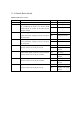
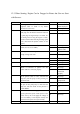
No. Operating steps Result Follow up steps
1 Insert the ignition key into the ignition lock. Next step
Yes Check other part 2 Put the ignition switch to ON position, and then
observe if engine failure indicator lamp or EPC
lamp works normally (quick flash of failure
indicator lamp or EPC lamp indicates a abnormal
condition).
No Next step
Yes Remove the failure
and clear the DTC
3 Connect a diagnostic tester to the system, and then
enter corresponding diagnostic program unit to
check if DTC exists in the system.
No Next step
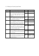
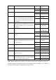
Yes Next step 4 Pull out theft-proof module joint on harness, and
then use a multimeter to check if an around 12V
operating voltage is present on A1#, A4# pins of
the joint when ignition switch is under ON state.
No Check the circuit
Yes Check the circuit 5 Pull out theft-proof module joint on harness, and
then use a multimeter to check if such electric and
circuit failures as short circuit and break circuit
exist in the circuit between A5#, A8# pins of this
joint and 31# and 71# pins of ECU.
No Next step
Yes Check the circuit 6 Pull out theft-proof module joint on harness, and
then use a multimeter to check if poor contact
exists between A2# pin of this joint and ground
wire of the vehicle.
No Next step
Yes Check the circuit 7 Pull out theft-proof module joint on harness, and
then use Ohm Shift of the multimeter to check if
the circuit between B1#, B2#, B3# pins of this
joint and the coil exists.
No Replace the
theft-proof module