Preface ADVICE User’s Manual clarifies the agreement between Chery Automobile Co., Ltd. and the User on the product quality warranty responsibility and the establishment and termination of after-sales service rights and responsibilities. Please read this User’s Manual carefully before using our products. User’s Manual for Chery V5 Sincere congratulations on your own of one Chery V5! Also, with great appreciation on your great favor on our company and our products.
Preface This manual is established based on the detailed conditions of V5 vehicles manufactured by Chery Automobile Co., Ltd., which only applies to the V5 vehicles manufactured by Chery Automobile Co., Ltd. This manual included the latest information up to the date when this manual is printed. Chery Automobile Co., Ltd. will be wholly responsible for the modification and explanation of this manual and reserved the rights for product replacement after the print of this manual without any prior notice.
Summary Chapter 1 Summary 3
Summary vehicle driving as well as enjoy the Before reading this User’s Manual, you should understand following things. pleasure thereof. This Any improper operation may damage your claim right. The periodical maintenance to your In order to operate your vehicle properly performance and used value of your and guarantee your rights and benefits, vehicle. The Chery authorized service please spend some time to read this stations all over the country boasted manual carefully.
Summary explanation for the alarm symbols with disposing the used cleaning articles and The dealer should verify the entire vehicle triangle. Please read carefully and abide lubricating materials in accordance with performance and introduce the operation by the contents thereof. the laws and regulations. This manual knowledge of the vehicle against the displayed the information on this aspect by “Chery Vehicle Sale & Delivery Card” means of tree symbol.
Summary tachometer, the allowed short period top the beginning of use; therefore, the tires engine speed is 6,000 r/min. During the also need run in. The vehicle speed should Run in Regulation within 1,000 km manual gearshift, make sure to shift to the be relative low during first 100 km driving next high gear when the engine tachometer and the driving should be extremely y Full speed driving is absolutely indicator reached red indication area at the careful. prohibited. latest.
Summary if the wheel has been replaced or the wheel nuts have been loosened, then the wheel nuts should be re-tightened in accordance with the specified torque after traveled for 800km. “One-To-One” Service In order to provide you with better service and vehicle use, the dealer of Chery Company will appoint one service counsel to serve you at the purchase of your vehicle. In case of any problems during your vehicle use, you may contact your service counsel, who will provide you with best services.
Summary Vehicle Delivery Inspection Evidence This is to certify that this vehicle has completed the vehicle delivery inspection defined by Chery Automobile Co., Ltd. and its quality met with the technical specification of Chery Automobile Co., Ltd. Vehicle Register No.
Summary Vehicle Delivery Date Dealer Stamp Model: Body VIN No: Engine Serial No.: Transmission Serial No.
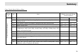
Summary Chery Vehicle Sale & Delivery Sheet Entire Vehicle Performance Catego ry No. Item Whether inspected OK and clearly explained 1 Engine Yes □ No □ 2 Engine oil, brake liquid, steering liquid, coolant, battery liquid, windscreen cleaning liquid.
Summary 1 93# gasoline fuel Yes □ No □ 2 Normal operation during run in. Yes □ No □ 3 Operation of entire vehicle lamps Yes □ No □ 4 Meaning of alarm indicators Yes □ No □ 5 Correct maintenance period and mileage Yes □ No □ wled 6 Vehicle maintenance items in winter and summer. Yes □ No □ ge 7 Correct understanding of cooling system/coolant usage.
Summary Vehicle Purchase Date Model: Following items should be validated by the user: I. Related items confirmation at vehicle delivery (“√" for Yes as “×” for No) □ Basic vehicle operation method has been introduced and the onsite delivery inspection is certified OK. □ Quality warranty policy has been introduced. □ Vehicle driving notices has been introduced. □ The importance of vehicle periodical maintenance and maintenance period/mileage has been introduced.
Summary User Name: Sales Agency: Vehicle VIN Number: Vehicle Purchase Date Model: Following items should be validated by the user: I. Related items confirmation at vehicle delivery (“√" for Yes as “×” for No) □ Basic vehicle operation method has been introduced and the onsite delivery inspection is certified OK. □ Quality warranty policy has been introduced. □ Vehicle driving notices has been introduced.
Interior Device Operation and Adjustment Common Vehicle Symbol Instruction Symbol A/C Definition Symbol Definition Symbol Definition Engine self-examination trouble light Anti-lock system Glass lifter switch prohibited Safety warning Engine oil pressure alarm lamp Rear fog light Throttle indicator Coolant temperature overheating alarm (red indicator) brake trouble Position lamp Front fog light Cigarette lighter Coolant temperature normal indicator (green indicator) A/C system Brake tro
Interior Device Operation and Adjustment Symbol Definition Symbol Definition Symbol Definition Battery Fasten the safety belt Windscreen cleaning High beam lamp Danger alarm lamp Horn Low beam lamp Power + pole Seat heating Head lamp switch Air bag trouble indicator Windscreen defrosting Parking indicator Low fuel level alarm indicator Rear windscreen heating indicator External rear view mirror heating External circulation Lock indicator brake flash air 16
Interior Device Operation and Adjustment Symbol Definition Symbol Definition Symbol Definition Unlock indicator Interior lamp switch indicator Internal circulation Door and luggage boot cover not closed alarm lamp Sound alarm Air bag identification Vehicle maintenance indicator Right indicator turn air Left turn indicator 17
Interior Device Operation and Adjustment Symbol Definition Transmission gear position indicator Backup radar distance display Fuel consumption display 18
Interior Device Operation and Adjustment Chapter 2 Interior Device Operation and Adjustment 19
Interior Device Operation and Adjustment Steering Wheel/ Ignition Switch The combined steering wheel lock/ignition switch has following key positions: LOCK - Ignition switch is turned off as the steering wheel is locked. When the key is pulled out from the ignition switch, the steering wheel lock will actuate to lock the steering wheel. In order to lock the steering wheel, rotate the steering wheel once after the withdrawal of the key, till the engagement sound as the steering wheel is locked.
Interior Device Operation and Adjustment Horn In order to drive the vehicle safely and comfort, sometimes the height of the steering wheel should be adjusted. At such time, pull downward the adjustment handle under the steering pillar cover to release the handle and then the steering wheel can slide up-and-down. After adjusted to position, pull upward the adjustment handle to lock position and lock the position of steering wheel. Do not adjust the steering wheel during driving.
Interior Device Operation and Adjustment the ignition switch is turned on. The Move the control lever downward from front windscreen switch totally has 5 OFF position to INT gear after passing positions and will stop at OFF position through one position. when unused. The wiper controller will operate automatically once for every certain Single Wiping interval. Move the control lever downward from OFF position to HI gear after passing through three positions.
Interior Device Operation and Adjustment The operation period of water spray should not exceed 10 s for each time. This operation is absolutely prohibited when the reservoir has no cleaning liquid; otherwise it may cause the damage of the water spray motor. Rear Windscreen Switch Interior Review View Mirror window. The back of the sun visor can store the things such as driving license and Dazzling proof fork bridge & road passage fee invoice.
Interior Device Operation and Adjustment Electrical External View Mirror Rear it may fold the external rear view the right side. mirror inward manually. When to After rotate the adjustment switch leftward or rightward to position, pull Middle Position Left rear view mirror adjustment position adjust the external rear view mirror at Right rear view mirror adjustment position the switch toward front, rear, left, or right direction to adjust the up, down, left or right position of the mirror.
Interior Device Operation and Adjustment Rear Door Door window regulator switch Interior armrest function, namely the glass regulator switch is still operational within 60 s after the key is pulled out. The driver side door trim panel also has The electrical window will be operational only when the ignition switch is turned on. Each window can be operated by the control switch on the corresponding door trim panel. Each window glass has one-touch one safety switch button.
Interior Device Operation and Adjustment The heater of each seat will work when before releasing. When to empty the the corresponding switch is pressed. ashtray, remove the internal ashtray The further press of the switch will case to empty. stop the heating. Driver Seat Switch ( ) Driver side heater switch Rear row seat heater switch Heating Secondar y driver side heater switch Front Row Ashtray/ Cigarette Lighter Front row ashtray Cigarette lighter Located in front of the gearshift lever.
Interior Device Operation and Adjustment switch is turned off. Backup Radar System ( ) Do not leave the cigarette lighter at the inserted status for long period so as to avoid the danger. Please remove the cigarette lighter when leaving the child alone in the vehicle. sound from approximate 90 cm and the left/right rear corner radar probe will The backup radar assistant system is have rapid intermitted sound from the device to inform the driver when approximate 60 cm.
Interior Device Operation and Adjustment display will take 5 cm as one jump grade. The display will be 120 cm if the real distance is 123 cm. The parking radar probe will detect the nearest object. It should be noted that it may not detect the bumper of the vehicles with higher body height. Backup Radar Probe Position C Based on the change of the specification, the contents of this manual may differ from the real vehicle. Please accept our apology.
Interior Device Operation and Adjustment Whether the surface of radar probe is stuck with snow or mud. ● Whether the surface of the radar probe is frozen. ● Whether parked the vehicle in hot or cold weather for a long period. If all above items are excluded, please deliver your vehicle to Chery authorized service station for checking and repair. ● Please notice the following conditions, of which the radar probe may not alarm even closing to the obstacles.
Interior Device Operation and Adjustment It will not alarm the obstacles out of the detection scope. When having several obstacles, the backup radar probe will only alarm the obstacle with nearest distance. During the vehicle movement, please notice that the backup radar probe at another side may approach to other obstacles. Please notice the following conditions, which may result the wrong detection alarm. ● The thin objects such as steel wire, rope, wire net.
Interior Device Operation and Adjustment ● For the objects that hardly reflect the ultrasonic (as shown in figure below), it may not alarm depending on the shape of the obstacle. Pillar 柱 Thin 细tree 的树 Corrugated 瓦 楞 纸 paper Bicycle 自 行 车tire 胎 角材 Corner material 基 石 stone Base Front Passenger Bag (PAB) Switch Air It’s not allowed to take child at the front row passenger seat since the blown-out of the air bag will cause certain injury to the child.
Driving Chapter 3 Driving 33
Driving compartment and the exhaust pipe that may cause fire. Driving Start Preparation before Start The engine start is controlled by the engine electrical control system. Do not step the accelerator before start and during start when start the electrical injection engine. The accelerator should be used only when having difficult start. Please refer to the section “Engine Start” for the details of vehicle start.
Driving y The steering wheel is rotated during get-on and get-off (self-lock of the steering wheel). 6. At the same time when the ignition key is turned on, make sure that the dashboard alarm lamp lights shortly. If negative, then it needs to deliver your vehicle to the Chery authorized service station for overhaul. the first start. Instead, it should rotate the key to the OFF position and wait for 10 s before retry. 3.
Driving y When the sound of exhaust system is changed. Engine Speed Limit y When the vehicle is damage due to the collision. The engine speed is limited by the electrical control unit (ECU) so as to protect the engine. Ventilation Notice When the vehicle is parked in the open field for long period idle or when the persons rest in the vehicle, the window should be opened for at lease 2.5 cm. Or open the A/C system ventilation function to let the fresh air into the vehicle.
Driving more minutes so as to lower the engine temperature gradually. Turn off the ignition switch, the temperature will still be very high after the turn-off of the engine and the radiator electrical cooling fan will still keep running. Even the cooling fan stops running, it may run suddenly again due to excessive high temperature. Therefore, cautions should be taken when working near the engine so as to avoid the scalding.
Driving after replacement. The worn-out status of the brake lining depends on the working condition and driving method to large extent. For the vehicles mainly for city transportation, the working condition of the brake lining is relatively poor due to the frequent start and stop.
Driving The anti-lock brake system will not effect under normal brake period and will effect only when the wheels are almost locked. During braking, the pulse movement of the brake pedal together with the noise indicates that the ABS is under working. Such pulse movement and noise are normal. At such moment, do not release the pedal.
Driving Important Principle of Taking Advantage of ABS for Braking. Handbrake handbrake much easier. Operation of Automatic Transmission ( ) The automatic transmission in your vehicle is one kind of electrical controlled four-speed transmission with automatic gearshift mode. 1.Step down brake pedal and hold with full efforts. Pull up the handbrake handle after parking so as to avoid the humping due to temporary carelessness.
Driving Gear Selector Lever Position 41
Driving Make sure to pull up the handbrake handle before leaving the vehicle. P = Parking R = Reverse Gear SHIFT Lock LOCK = Gearshift When to move the gearshift lever without the stepping down of the brake pedal, please push down SHIFT LOCK (gearshift lock) key. N = Neutral Gear D = Drive Gear R = Reverse Gear + = Upshift This position must be shifted to during backup. - = Downshift This position can be shifted to only when the vehicle is completely still.
Driving 5. Under manual gearshift mode, the selected gear can be accepted only when the gearshift request conforms with the requirements of the transmission controller. 6. The braking no matter under manual gearshift mode or the automatic gearshift mode can achieve the automatic gearshift function without any gearshift operation; 7. The gear selector lever at “N” or “P” position during driving is strictly prohibited; otherwise the transmission will be damaged, for that Chery Automobile Co., Ltd.
Driving Display of R Position: Forced Downshift (Kick Down) Start Display of N Position: Display of D Position: Display of Manual Mode: Under manual gearshift mode, the selected gear by the driver will be displayed in digit type in the display screen. The figure takes gear 2 for instance.
Driving complained low horsepower (torque) during driving. In addition, when stepping down the accelerator slowly for acceleration, the engine tremble will even get bigger. Therefore, it should be avoided. Midway Stop When encountered with the red light or any other conditions that required the temporary stop, release the accelerator pedal and step down the brake pedal, with the gear selector lever remained at current position. When start again, release the brake pedal and step down the accelerator pedal.
Driving allowable for downshift. y Operation of Automatic Transmission ( ) Use/Operation Method and Notices: y y y y During gearshift, fully step down the clutch pedal to release the driver from the engine torque and then operate the gearshift lever for gearshift rapidly. The low speed gear should be used for downward slopes and turns. The slide with disengaged clutch is not allowed.
Driving y Whether the steering components is loosened or worn out. y Whether the wheel alignment is correct. Paddling If it’s must to paddle during journey, make sure to drive slowly and carefully, especially when having no knowledge of the water conditions. Do not drive forward further if the water can submerge the wheel hub. During paddling, the traction force and the brake performance of the vehicle will be lowered and the vehicle will have the danger of flameout.
Driving Notice: the engine. Chassis Protection The three-way catalytic converter will be getting very hot if the engine is under continuous running, therefore, notice to wear the protective glove during repair so as to avoid the scalding. y Run the engine under the condition that one spark plug cable terminal is removed. y Start the vehicle with the engine still at working temperature by means of pulling or hauling. Your vehicle is equipped with heat insulation plate.
Driving The above figure illustrates how the fuel consumption is influenced by the selection of vehicle speed and gear. Maintaining at low gear to improve the acceleration performance will result the obvious higher fuel consumption. Stroke Temperature Distance/Engine The frequent cold vehicle start and the short distance journeys will result the obvious increasing of the fuel consumption.
Driving After stop the vehicle and the engine, the radiator fan will continue running for certain period since the engine is still under hot condition and will stop running when the engine is cooled to certain temperature. Even though, the fan may still start suddenly in case of the sudden temperature increasing of the engine compartment due to the influence of the ambient environmental temperature (sunshine exposure or high temperature region).
Instrument Panel Chapter 4 Instrument Panel 51
Instrument Panel Instrument Cigar Lighter Horn switch Wiper switch Instrument Audio system A/C vent Steering wheel Panel Head Lamp Switch Dimmer control switch Adjustment switch of electrical regulated head lamp Coin box Air bag identification Front Fog Light Switch Front compartment cover pull-up switch Glove box A/C system Ashtray Rear Fog Light Switch Danger Alarm Lamp Switch Heating of rear windscreen 52
Instrument Panel Instrument ( Coolant temperature normal indicator lamp ) Door Ajar indicator Rear fog light Position lamp Front fog light lamp Brake system trouble alarm lamp Right turn indicator lamp High beam indicator lamp Left turn indicator lamp Engine trouble alarm lamp Maintenance EPC trouble alarm lamp reminding lamp ABS alarm lamp Coolant temperature high alarm lamp Parking indicator lamp Fuel gau Air bag alarm lamp Speedometer Gear display 53 Low fuel level alarm lamp
Instrument Panel related system if certain alarm lamp does When the ignition switch is turned on, not light or certain alarm lamp lights or this lamp will light shortly and at the flashes persistently after the engine is same time the ABS system will perform started. self-examination to determine if the system is capable of normal operation.
Instrument Panel Parking Brake Alarm Lamp send to the Chery authorized service station for checking. This lamp will take effect when the ignition switch is turned on. This lamp will keep light when the handbrake is pulled. Brake System Alarm Lamp This lamp will take effect when the The lighting of brake system alarm lamp during the driving indicates the trouble in one line of the dual brake circuits.
Instrument Panel When the ignition switch is turned on, Turn Signal Indicator Lamp Air Bag Alarm Lamp ( ) this alarm lamp will light and the engine electrical control system is under self-examination status. The alarm lamp will turn off within 6 s if such system has Comprised of left turn signal indicator lamp and right turn signal indicator lamp.
Instrument Panel When the ignition switch is turned on, Generator Alarm Lamp this indicator lamp will light before turn-off 3 s later. If this lamp does not turn off 3 s later or This alarm lamp will light when the this lamp lights during the driving, please ignition switch is turned on and will turn stop the vehicle immediately, stop the off when the engine is started. engine and check the engine oil level.
Instrument Panel Door Ajar indicator Lamp self-examination on the electrical throttle. the user to perform entire vehicle care The alarm lamp will turn off if such and maintenance in the service station. system has no trouble. The electrical throttle must be checked if the alarm Located in the centre of instrument central clock display screen. When the ignition switch is turned on, this lamp will light if whichever one of the four doors is not closed properly. lamp lights persistently.
Instrument Panel Passenger Side Air Bag Speedometer Indicator Lamp Standard fuel tank capacity: 61 L PAB When the pointer reached the fuel empty When the ignition switch is turned on, this lamp will light to remind the driver position “E” (as pointed by the arrow), the fuel tank has approximate 10 L fuel. to notice the switch position of the The pointer will move from full position passenger side air bag.
Instrument Panel Transmission Range indicator, Odometer, and Digital Clock The adjustment method The switch method of clock is as follows: between the clock, fuel consumption per 100 km Under the clock display status, the clock can be adjusted by pressing and holding the clock adjustment button on the The left upper corner will display the current transmission range . The right upper corner will display the clock, fuel consumption per 100 km, and the trip odometer (switchable).
Instrument Panel Tachometer The early shift to the high gear will help save the fuel and reduce the driving noise. Please shift to the next low gear immediately in case of the detection of unstable engine running. Do not run the engine at high speed during run in period. To display the engine speed ( r/min). The red area at the right side of the dial indicates the max allowable speed scope within short period under the engine working temperature after run in period.
Lamp Control Chapter 5 Lamp Control 63
Lamp Control Lamp Control Headlamp High /Low Beam Selector Switch Please abide by related traffic regulations when using the following illuminating equipment. Headlamp Switch Under the condition that the lamp gear 2 is turned on, pull the handle towards the console direction to shift into the high beam lamp after passing through the force application point. When the headlamp high beam is turned on, the OFF – Turn off the external lamp.
Lamp Control are located on the central console of the dashboard, the position between the audio equipment control panel and A/C control panel. When the headlamp switch is at gear 1 or gear 2 position, push down the front fog light switch to turn on the front fog light, but it can’t turn on the rear fog light directly. It needs to turn on the front fog light before turn on the rear fog light. When the front fog light is turned on, the indicator in the instrument will turn on.
Lamp Control Press again to turn off the lamp. The adjustment switch of electrical regulated headlamp is located on the left lower corner of the dashboard. Such switch has four gears of 0, 1, 2, and 3. The adjustment of four gears can adjust the light type of the electrical regulated headlamp.
Lamp Control status of the sunroof, press and hold the button ① for 0.5 s and then the rear part of sunroof glass will tilt down automatically (till closed position). Operation of Sunroof Sun Visor 3 ! Notice: ▲ The sunroof can’t actuate the slide down and the tilt up at the same time, therefore, it can’t tilt up when under slide down status as well as can’t slide down when under tilt up status. It can actuate the tilt up or slide down after the sunroof is closed.
Lamp Control Interior Lamp Rear Ceiling Such lamp will light when the luggage boot cover is opened (This lamp is not subject to the control of ignition switch). Please notice to close the luggage boot cover securely after parking. ! Notice: The following operations will result the lost of sunroof module initial memory. During the vehicle maintenance, such problem will present when the battery is replaced or the power supply is pulled out under the condition that the sunroof not at initial position.
Lamp Control This switch is located on the instrument central console, the position between the audio equipment panel and A/C control panel. This alarm lamp should be used only under emergent conditions so as to alarm the following vehicles that this vehicle has trouble or danger. Push down this switch to turn on/turn off this system. The danger flash lamp is operational when the ignition switch is turned off. The indicator on the switch will flash after the alarm lamp is turned on.
Door Lock and Anti-Theft Chapter 6 Door Lock and Anti-Theft 71
Door Lock and Anti-Theft Door Lock and Anti-Theft Vehicle Key and Remote Controller key popup key on the remote controller. At the complete of use, you may fold the key back to facilitate your carrying. Lock Central Lock System Unlock move downward during lock. Also, it can lock the door by pushing down the safety switch. In order to avoid the ingress of foreign force into the vehicle during driving, please drive your vehicle with the doors fully locked.
Door Lock and Anti-Theft the vehicle. Child safety lock The doors will be locked automatically when the vehicle speed reached 35~45 km/h. Each engine start will only have once automatic lock function. If the central lock function is activated or relieved when stop the vehicle during driving, then it has no automatic lock function when the vehicle reached 35~45 km/h again. The lock will be automatically relieved after parking and engine flameout.
Door Lock and Anti-Theft Release Rod of Filler Cap fuel tank cap can be placed on the filler cap. Open Engine Compartment Cover 3. 4. Pull up the release rod at the left of the driver seat to open the filler cap. 1. 2. As shown in the figure, the screwed off Pull up here outward The pulling handle of engine compartment cover is located on the left lower corner of the instrument panel. The engine compartment cover will bounce up for certain length by pulling the pulling handle rearward.
Door Lock and Anti-Theft engaged. Make sure to lock the engine compartment cover securely during driving. In case of the detection that the engine compartment cover is not closed securely during driving, stop the vehicle immediately and close it securely. Remote Control System with Anti-Theft Function ( ) The effects of this system are to stop the unauthorized personnel to open the door, luggage boot or the engine cover.
Door Lock and Anti-Theft Remote Controller Battery Replacement The battery should be replaced if the action distance of the remote controller is shortened gradually (battery type: 3V CR 2032). Perform in accordance with following steps: 1. Open the remote controller unit from the side clip with flat nose tool. 2. Pry out the battery carefully. Install the new battery between the two terminals with the symbol (+) facing upward. 3. Install the remote controller unit in reverse order.
Seat and Safety Protection Chapter 7 Seat and Safety Protection Device 77
Seat and Safety Protection Seat and Safety Protection Rear Seat Row Central Row Seat Front Seat Row 78
Seat and Safety Protection y Seat and Safety Protection y Seat Max. 25° y Adjust the headrest properly to level the top end of headrest to the top end of the head. Do not make the front seat close to the dashboard too much. Grasp the steering wheel with slightly bended arm during driving. The foot should also be slightly bended so that it's capable of stepping down the pedal to the end.
Seat and Safety Protection Front Row Passenger Seat Adjustment Adjustment of front row seat seatback inclination degree Firstly, lean on the seat seatback with the body, trip the seat right seatback adjustment handle, and adjust the seatback to the needed angle by changing the body inclination angle.
Seat and Safety Protection external side of the headrest guiding element and at the same time pull out the headrest from the guiding element. During the assembling of the headrest, firstly distinguish the front/rear seat headrest (the front seat headrest is bigger than the rear seat headrest) and then push the headrest pin into the guiding element, till the spring clip on the guiding element engages with the pin correctly.
Seat and Safety Protection position by pulling the pull belt. Adjustment of Seat Seatback Inclination Angle Trip the seat seatback adjustment handle to change the central row seat seatback inclination angle. The method is same with the one of front row seat seatback inclination angle. Seatback Adjustment Handle Folding of Central Row Seat This vehicle can realize the multi space combination to satisfy various demands based on the folding combination of the vehicle seats.
Seat and Safety Protection The seatback can be folded to the shown position by pulling the seat seatback adjustment handle. Rear Row Seat Folding of Rear Row Seat Seat Reset According to the following illustration, reset the central row seat to the original status. Central Row Seat Armrest The middle of central row seat seatback has armrest that can be rolled over on the cushion from the seatback by pulling the pull belt.
Seat and Safety Protection The back of the rear row seat has the pull belt that facilitating the lift of seatback from the rear. Please fix the articles securely from movement if the articles must be placed inside the vehicle. Try to load the luggage and other loading articles as forward as possible in the luggage boot. It’s extremely dangerous to drive the vehicle with opened tailgate. The excessive exhaust gas may be inhaled into the vehicle through the opened luggage boot door.
Seat and Safety Protection the central row seat themselves and at the same time the seat will slide forward automatically to make space for the get-off of rear row passengers. collide inside the vehicle or may be thrown out of the vehicle in sudden brake or accident, which may result the severe injury or death.
Seat and Safety Protection safety belt can’t be shared by multi persons. Make sure the safety belt is fastened without any looseness, twist or obstacle. The driver and the passenger at the front row are required to fasten the safety belt securely during driving. Avoid wearing the wide and thick clothes. In order to achieve best protection effects, the seat safety belt should cling to the body. Seat Safety Belt Alarm Lamp This alarm lamp will light when the ignition switch is turned on.
Seat and Safety Protection cross the middle of the external shoulder, then release the lock button and shake the adjuster to make sure the adjuster is locked. Maintenance of Seat Safety Belt Checking of Seat Safety Belt Do not try to repair or lubricate the safety belt retractor or the buckle mechanism and do not change the safety belt with any means, otherwise Chery Automobile Co., Ltd. will not be liable for the problems arisen.
Seat and Safety Protection guarantee that the body is at such position that the air bag can exert the best effects. Front Air Bag Extreme danger! Do not use the reverse direction child seat on the seat equipped with front air bag. posture with the lower end of the back clings to the seatback as tight as possible and the rearward inclination angle of the seatback should not exceed 25 degrees. Do not make the front seat close to the instrument panel too much.
Seat and Safety Protection authorized service station for checking. The manufacturer for the air bag that equipped on this vehicle recommends renewing the air bag after equipped for 10 years, at that moment the efficiency of the inflating agent and the effectiveness of the air bag is deteriorated. If you have any doubts against the service length of your vehicle/air bag, Chery authorized service station is willing to query the related data for you.
Seat and Safety Protection Driving Direction y The child between 4 years and 12 years old or between 18 kg and 36 kg weight should sit on the rear seat with heightened cushion. The adjustable assistant safety belt that fixed on the heightened cushion can ensure that the diagonal safety belt crosses the shoulder properly.
Audio Chapter 8 Audio Part Please read the user’s manual for audio system onboard carefully if the vehicle is equipped with other than following audio system.
Audio DVD Part ( ) 92
Audio Main Function ★ Five wave bands of FM1, FM2, FM3, AM1 and AM2 that capable of saving 6 radio channels each. ★ Auto/manual channel search ★ Automatic channel saving/ programmed channel saving ★ Preview of saved channels Play of Multi-Media DVD/VCD/CD/MP3 ★ Sequent play to play each song in turn. ★ Capable of power cut memory point play function. ★ Capable of multi-media entertainment function and identifying automatically the media discs in DVD, VCD, CD and MP3 format.
Audio 1. Temperature Issue 1) This device may not function normally under extreme cold and hot conditions and this device will resume operation when the temperature restores to ambient temperature. 2) Do not place the device in the hot places (such as the places with direct sunshine and inside the vehicle under hot summer days) and cold places; otherwise the device may have malfunction or deformation. 3) The normal operating temperature range of this device is -10℃~+50 ℃.
Audio is easy to contaminate the dust. Cut the power supply during cleaning and wipe with soft cotton cloth. Please do not use the wet wiping cloth nor wipe or knock with hard object. 2) The surface of the cabinet and panel will be corroded if contaminated with gasoline, thinner and volatile agents such as pesticide. Please do not use such things. About CD Multi-Media, DVD, CD, MP3 DVD left logo. CD Please use the discs with Please use the discs with left logo.
Audio Operation Panel Illustration Panel Illustration and Illustration Automatic light measurement receiver. The function definition for keys is shown in the right table. Icon Display Illustration DVD: Indicated that DVD function is currently in use.
Audio Power On/Power Operation Illustration Radio: Indicated currently in use. that radio is Stereo: Indicated that the radio currently plays stereo programs. CD: Indicate that the DVD_ROM player currently has disc inside. Vehicle Alarm: Indicated that some vehicle functions currently have faults. Mute: Indicated that the system is under mute mode; Remote: Indicated that the current playing radio is other than local radio programs.
Audio connected (vehicle key signal is ineffective), the system can power on for operation. After power on, the system will run no more than 1 hour; otherwise the system will power off automatically. Before the vehicle circuits are connected, the system will not respond to any operation of the POWER key so as to protect the vehicle battery power from excessive consumption.
Audio procedure before the power cut. Radio Press key to enter into radio mode and play the current channel with the menu shown in following figure: Please refer to the table for the operations of function keys. The keys not included in the table will have no response.
Audio Preview of Saved Channels Under radio interface, press key and the device will enter into the browse status of the saved channels to browse the saved channels under current waveband. During the preview of saved channels, the device will automatically search the information of saved 6 radio channels under current waveband with 5 seconds play for each channel.
Audio will have no response. of function keys. The keys not included in the table will have no response. Automatic Search Under the radio interface, press key and the device will automatically search the radio channels under current wave band. During the automatic search, the device will automatically conduct one overall search of the current radio waveband and automatically save the searched radio channels in the 1~6 memory units.
Audio Information Menu Press key to enter into information menu with the menu display shown in the following figure: Please refer to the table for the operations of function keys. The keys not included in the table will have no response. Note: The information menu will automatically return to original function after 5 seconds. It also can directly exit the information menu by function key to pressing the return to original main function.
Audio default setup). Audio Setup Under information menu, press key to enter into audio setup interface with the menu shown in following figure: The setup of audio effects will directly affect the audio output of system all products. Please refer to the table for the operations of function keys. The keys not included in the table will have no response. Audio function setup includes following contents: 1) Audio effects adjustment Standard (default), pop, jazz, classic, beat, and rock.
Audio the visual difference so as to achieve Video Setup Under information menu, press key to enter into video setup interface with the menu shown in following figure: Auto light Hue Palette The video function can adjust the automatic light measurement, palette, hue, brightness, contrast, saturation, and restore to default.
Audio Time Setup Under information menu, press key to enter into time setup interface with the menu shown in following figure: The time setup function is for the adjustment of the time. Time: Including the selection of 12-Hour and 24-Hour (24-Hour in default). Also it can calibrate the year, month, day, hour, and minute. Please refer to the table for the operations of function keys. The keys not included in the table will have no response.
Audio Disc Play When press key, the system will enter into disc play function and will automatically detect the disc contents in the DVD-ROM drive. During this period, the system pre-reading time will be much longer. At that moment, there has one transitional interface as shown in following figure. This device may not respond to the user’s operation during loading disc data. Please refer to the table for the operations of function keys. The keys not included in the table will have no response.
Audio DVD/VCD Function DVD_ROM DVD/VCD DVD/VCD If place the DVD disc into the DVD, the system will start normal play. Please refer to the table for the operations of function keys. The keys not included in the table will have no response.
Audio CD Function If place CD disc into the DVD_ROM, the system will start normal play with the interface as shown in the following figure. (The time and song number are shown in the left upper corner) Please refer to the table for the operations of function keys. The keys not included in the table will have no response.
Audio MP3 Function If place the MP3 disc in the DVD_ROM, the system will display the folders of current disc. Please refer to the table for the operations of function keys. The keys not included in the table will have no response.
Audio After enter into the folder where the songs locate, it will display the songs in MP3 format under current folder. Please refer to the table for the operations of function keys. The keys not included in the table will have no response.
Audio Front/Rear Balance Options STEREO【Stereo】 L-CH【Left Mono】 R-CH【Right Mono】 3) Automatic power off of the device: Please check if the vehicle key is inserted properly or if using this device for 1 hour without the vehicle key. Please conduct adjustment or selection in accordance with following operations: 4) After press key, the display screen of the device will automatically return within 15 s. The disc jam should be noticed.
Audio 9) When at power off, the display screen of this device will not retract normally if 10) If the device has operation function failure or abnormal conditions, please conduct device reset in accordance with the following operations. The device will resume normal after power on. encountered with disc jam or obstacles in movement direction.
A/C System C 113
A/C System hapter 9 A/C System 114
A/C System A/C System Ventilation The outside air enters into the vehicle via the air inlet located in the front of windscreen. Please keep the air inlet under the windscreen without snow, tree leaves and etc. in order to ensure that the warming and ventilation function can normally, effectively works.
A/C System Windscreen vent Side defrost vent Side defrost vent Instrument panel vent Floor vent 116
A/C System Max. airflow air flow and direction. Air cleaner The air cleaner can guarantee that the deleterious particles such as flower powder, industrial dust fall, road dust and etc are removed from the air before Precautions on the regulation of vent (the vent is regulated on demand): the air passage and vent jammed enable the air output to be bad Shut down the center and lateral vents to make the max. airflow flow to the pedal or windscreen. it enters into the vehicle.
A/C System Electronic control AUTO A/C System Internal/external cycle Outside Temp AUTO mode A/C Display Panel OFF Air volume + Mode Control A/C Compressor Defrost ON/OFF Air volume - 118
A/C System A/C display panel Temp Display Defrost AUTO Mode Internal Cycle External Cycle Foot Face COOL mode Blower Run Blower Position Note: A part of symbols of A/C system are displayed in the figure above. When the A/C system runs, some symbols will not appear. The related symbol appears only in case of the corresponding run mode. So, these symbols represent the current run mode of A/C System, which will be described in the following.
A/C System The A/C system is controlled by the electronic circuit and micro motor which are designated to determine the position of inlet and outlet of A/C system. The electronic circuit is also designated to control the following functions • Mode operation • A/C compressor clutch operation • Fan operation • Exhaust temperature A driver can use the A/C control panel to select any of the following functions • Inside temperature • Blower speed • Five different operation modes 1.
A/C System closes and all actuating mechanisms shut down at the same time and stop operating. 6.
A/C System The air volume decreases one gear every one press of the pushbutton until down to ZERO gear (min.).
Emergency Procedures Economy run of A/C system The A/C compressor consumes the power of engine during cooling, and thus enables the fuel consumption to increase. To save the energy and reduce the fuel consumption, please SHUTDOWN the A/C system when it is not on demand. If there is high temperature in the compartment of parked vehicle due to the sunshine, it is recommended to open the windows or doors to dissipate the hot air. It is helpful to improve the cooling effect and reduce the fuel consumption.
Emergency Procedures 2. Press the “Internal Cycle” pushbutton, and select the inside air cycle mode. 3. Set the temperature to “LO”. 4. Reset the temperature to the comfort temperature after the temperature decreases. Recommendation: If the AUTO A/C system is used in the hot whether, please keep it on the inside air cycle state, which may reach the best cooling effect and separate it from the outside foreign odor.
Emergency Procedures Rear windscreen defrosting Press the defrost heater switch to remove the cat ice and mist from the rear windscreen. The rear windscreen-defrosting heater can work only after the ignition circuit turns on. Press the electric heater switch to turn ON/OFF the heating system. After the heater turns on, the indicator light on the switch lights, which shows that the heater is heating.
Emergency Procedures Chapter 10 Emergency Procedures 126
Emergency Procedures Emergency flasher light. When the ignition switch When the fuel level is extremely low, turns off, the hazard warning flasher the engine will operate unsteadily light still can operate. within a period of time after the low fuel indicator lamp lights, which is Procedures Partial operation served as an additional alarm. In this The engine control system of the case, please drive your vehicle to the vehicle nearest gas station to refuel.
Emergency Procedures y If the automatic compressor gun avoid that the fuel overflows from DO NOT directly hold the glass of bulb is automatic the fuel can and thus a fire by hand, otherwise the fingerprints shutdown of the gun during available, the disaster occurs when an accident remained on the glass will be heated refueling indicates that the fuel is met. and volatilize after the lamp lights, and tank is fully refueled.
Emergency Procedures Turn signal, back-up, Stop/position rear fog lamps bulb: bulb: lamp after the headlamp unit is removed. 1. bonnet. 2. 12V 21W 12V 21W/ 5W License plate, position, turn signal bulb: Unscrew the protecting hoods from the low beam and the high beam bulb in the anticlockwise Front fog lamp bulb: direction according to the position as shown in the diagram.
Emergency Procedures bulb. The lighting system is a safety component, please pay more attention on the replacement of it and ensure that any detail must be proper in case of Front fog lamp bulb anticlockwise direction, remove the harness connector Please get to the Chery’s special from the tail lamp, and take out service station to replace the front fog the tail lamp. lamp bulb. replacement. Get to the Chery’s special service station to have it repaired, if the 2.
Emergency Procedures order to avoid it affects the brightness of the bulb. The lighting system is a safety component, please pay more attention on the replacement of it and ensure that any detail must be High-mount stop lamp bulb The high-mount stop lamp bulb can’t be replaced. If the bulb fails to work, please immediately get to the Chery’s station to have it repaired, if necessary. The position lamp bulb can’t be replaced. If the bulb fails to work, 1. Turn off the interior lights. repaired. 2.
Emergency Procedures the bulb. relation with the safety of travel. So, it spare fuses with the vehicle in order to is allowable to regulate the beam only prevent some unexpected events. Luggage boot lamp bulb using the special instrument. During Installation position: On the side of adjustment, please abide by the laws luggage boot. and regulations concerned. 1. Insert the screwdriver into the gap between the lamp housing and lampshade, and carefully take out the lampshade. 2.
Emergency Procedures Replace the fuse Fuse Color Code Any unauthorized alteration of the vehicle’s electrical or fuel system may make an influence on the performance of the vehicle and cause the fire disaster or potential hazard. So, it is recommended that any work related to the removal of fuel or electrical system and the replacement of relay shall be conducted by the Chery’s special service station. Color Current (A) Tan 5 Brown 7.
Emergency Procedures Engine compartment fuse box: The fuse box is located at the right side of engine compartment and at the rear of battery. When the fuse is checked or replaced, loosen the claw and then pull up the bonnet to remove the fuse box cover plate (“B+” is the main power supply of fuse box).
Emergency Procedures Replace the wheel Before the vehicle is lifted up, please stick to the following precautions. Stop your vehicle on a proper location, please make sure that it neither affect the traffic, nor endanger your safety Spare wheel unscrew the glove box fixing bolts (each one at right and left If the dimension of some one wheel (either steel ring or tire) is different from that of other wheels installed, please abide by the following regulations. sides) in the anticlockwise direction.
Emergency Procedures To lift up the vehicle using a jack is suitable for the replacement of wheel only. In this case, DO NOT operate under the bottom of vehicle. convex part. The position shall be close to the wheel to be repaired A.S.A.P. Groove 3. When the towing hook bolt is unscrewed, detach the towing hook from the support used to fix the tire and then take out the spare tire. (Reinstall the tire in The max. working load of jack is 1,000Kg. the reverse order.
Emergency Procedures 4. Install the wheel Tell the passengers to leave the vehicle. 5. 6. 1. If necessary, use the proper wheel tighten the wheel nut in the stopper to secure the vehicle in clockwise direction and make order to avoid the roll or slide. sure that the tip of wheel nut faces to the wheel. Insert the flat head screwdriver 2. into the gap between the steel Lower the vehicle and remove the jack. ring and hub cap, and carefully turn it to remove the hub cap. 7.
Emergency Procedures Chery’s special service station to on the glove and safety goggles. check the tightening torque of DO NOT let the acid or lead wheel nut and the tire pressure. touch your skin or clothes. DO y Keep the children away from the battery acid. NOT tilt the battery, otherwise the acid may flow out from the vent. Battery If the acid splashes into your eye, Recommendations on safety to wash your eye for several When the battery is delivered, take the following countermeasures.
Emergency Procedures current and capacity of new battery must be the same as that of old battery or conform the Chery’s specifications. For the y There is high voltage in the proper electronic ignition system. Please please contact the Chery’s special DO NOT touch these components service station. when the engine is operating or y the ignition switch turns on.
Emergency Procedures Engine battery-assisted start method 1. order to avoid that they don’t Connect the down-lead If there is no power in the vehicle’s touch each other. 2. battery, introduce the power of other equipment. engine to start. 3.
Emergency Procedures 4. Connect one terminal of wire B to the negative (-) terminal of the support battery, the other terminal to the metal part of the engine to be started. Position the jumper wire in order to avoid it contacts the motion parts in the engine To reduce the voltage surge during removal, please turn on the blower and electric heating type rear windscreen of the vehicle with low power battery.
Repair and Maintenance Chapter 11 Repair and Maintenance 143
Repair and Maintenance It is essential to take the regular maintenance on your vehicle during the Care and course of use. Please implement the are recommended in the Instruction Manual. Otherwise, it may damage your vehicle.
Repair and Maintenance strict professional training organized and braking function are normal. Check by the Chery Automobile Co., Ltd.. the warning lights. (See the Regular General maintenance for a vehicle They will do their best to offer you Maintenance Schedule below for your The washing area where the the best high-quality after-sale service. reference) . ecological If you dissatisfy the work of the Chery’s special service station, please feel free to email it to: Cheryservice@myChery.
Repair and Maintenance Maintenance Schedule CAUTION: * Monthly check: Daily check: y Coolant level (for engine cold state) Check the working condition of all exterior and interior lamps and lights. The air conditioner shall operate for y Whether or not there is leakage Replace the damaged or dim bulbs, in the assy., pipelines, hoses and and make sure that all mirrors are oil reservoirs clean.
Repair and Maintenance Engine compartment maintenance items Brake Fluid Reservoir Engine Oil Dipstick Coolant Reservoir Power Steering Fluid Reservoir Air Cleaner Fuse Box Battery Windscreen Cleaning Fluid Reservoir Engine Oil Filler Cap Automatic Transmission Oil Dipstick 147
Repair and Maintenance the normal working temperature of the Engine oil dipstick Engine oil filler cap engine is still unavailable). Before the engine oil is checked, DO NOT start the engine at the cold state. Draw out the oil dipstick MAX MIN The engine oil is affected by many factors. A new engine reaches the normal operating specification only after traveling approx. 5,000 Km. More engine oil might be consumed when the engine operates with high load. Regularly check the engine oil, e.g.
Repair and Maintenance The household waste Engine coolant reservoir is unallowable to be placed into the empty oil container and disposed. When these wastes are disposed, please 储液壶位于 engine 仓右后部. 油位必 make use of the local waste disposal The level of oil shall be between the MIN facilities qualified. and MAX marks at the reservoir side. If the level of oil drops down to the MIN Brake fluid/clutch oil Please DO NOT let this fluid contact your skin or eye.
Repair and Maintenance the reservoir cap a quarter turn to relieve the accumulated pressure. Then, fully open the cap after a period of time. Refill the coolant suitable for the specification Please DO NOT use the coolants with different colors and specifications. of the vehicle. protection for a engine. So, please use the drop down any more, and then screw on coolant which conforms to the Chery’s specifications. DO NOT use the tap water to substitute the coolant.
Repair and Maintenance automatic transmission oil once every 40,000 Km road mileage. During the routine examination, if it is found that the color of transmission oil becomes black, brown or there are obvious foreign materials in the oil, replace level of fluid shall reach the MAX mark. If the level is below the new battery must be the same as that of MIN mark, please refill the specified fluids. the used battery or conform to Chery’s specifications.
Repair and Maintenance Please screw up the reservoir cap after refilling. Replace the wiper blade the details, refer to the tire pressure recommended in the chapter “Capacity and Specification”. Check the wiper blade Comply with the correct tire pressure in particular when the vehicle travels at heavy load and high speed. The tire pressure insufficient may reduce the Raise the wiper arm until it is perpendicular to the wiper blade.
Repair and Maintenance The improper tire and wheel rim may result the traffic accident, without the warranty. Dispose the worn tire according to local use the genuine tire when the tire is regulations on environmental protection. installed Change the winter tire to summer tire as recommendation from the Chery’s special soon as road condition permits, which service station. wear on the surface of tire.
Repair and Maintenance When the snow tire chain is in service, Drive belt CAUTION: the performance of the vehicle equipped with the snow tire chain control system The drive belt is one of the parts subject may be somewhat abnormal, and this to the most severe stress. Therefore, the The driving belt may somewhat extend symptom can be removed when the belt must be of high quality and reliable after it is in service for a certain time, and system shuts down. to meet operational needs.
Repair and Maintenance Use the cold or slightly-warmed water to wash the vehicle only. the belt: Max. allowable flexibility: 10 mm. 3. If the flexibility allowable exceeds value, After the vehicle is cleaned, step on the brake pedal service times to remove the moisture from the brake disc during the journey. please special service station to have it regulated. Clean the headlamp Automatic vehicle washer Wash the vehicle DO NOT throw the cleaning materials into the household waste.
Repair and Maintenance Chassis anti-corrosion The vehicle’s chassis has already conducted the anti-corrosion treatment. Regularly anti-corrosion check the protection, chassis and, if damage the special machined surface. Paintwork protection The cleaning products Wax your vehicle once or twice every year to keep the paintwork smooth, To get the best effect, please properly use better. the vehicle care products.
Repair and Maintenance Clean the radiator After the vehicle travels for a period of time, the windward side of the condenser and radiator may be jammed by some insects, tree leaves, and other foreign materials. In this case, it will make an influence on the performance of the air conditioner and cooling system, which results the air conditioner failure to operate normally, cooling system over-heat and etc. So, it is necessary to clean the radiator and condenser.
Repair and Maintenance Mileage (Km) Maintenance Item 5,000 15,000 30,000 Lighting, warning flasher devices, horn: Check the performance ★ ★ Wiper and cleaning equipment: Check the performance, and add the cleaning fluid, if necessary ★ ★ Check the free travel of clutch and the clutch fluid level, and regulate it, if necessary ★ ★ Engine oil: Replace it ★ ★ ★ Oil cleaner: Replace it ★ ★ ★ Transmission oil: Check the level of oil, color and quality of oil, and refill it, if necessary ★
Repair and Maintenance Mileage (Km) Maintenance Item 5,000 15,000 Fuel cleaner: Replace it 30,000 ★ Wedge-shaped belt: Check the tension, and regulate or replace it, if necessary ★ ★ Transmission: Check the leakage or damage ★ ★ Dust cap of constant velocity universal joint: Check whether or not it is damaged ★ ★ ★ Steering tie rod end: Check the clearance and whether or not the dust cap is damaged ★ ★ ★ Protective sleeve of steering universal joint assy.
Repair and Maintenance Mileage (Km) Maintenance Item 5,000 15,000 30,000 Universal joint/front wheel bearing: Check whether the connection is loose, and the abnormal sound ★ Engine oil sump bolt: Check whether or not it is loosen, and tighten it, if necessary ★ Control arm rubber sleeve: Check whether or not it is damaged ★ ★ Brake hose: Check whether or not it is aged or damaged ★ ★ Brake pipe: Check whether or not it is damaged or corroded, and the leakage of all joints ★ ★ ★ ★ Suspensi
Repair and Maintenance Mileage (Km) Maintenance Item A/C system: Check whether or not its pressure is normal, check the leakage, abnormal sound, abnormal odor, and whether or not the system works normally Tire (incl.
Repair and Maintenance Chery First 5,000Km Maintenance Card (Within six(6) months as of purchase date) Special service station (stamp) Vehicle Profile Date: _______________ Owner: ___________________ Company (Name: _________________ Address: ________________________ Telephone: ________________________ E-Mail: _____________________ Purchase Date: ____________________ Purpose: ____________________ License plate number: ____________________ Mileage: Chassis No _______________ Model Purpose: __________
Repair and Maintenance Fist 5,000 Km Maintenance Card (Within six(6) months as of purchase date) Date: ____________ Mileage: ____________ Items to be checked: Yes No Items to be checked: Yes No 1. Check the leakage of lubricating system, □ □ 11. Check the tension of generator and air □ □ cooling system and fuel system. conditioner belts, and regulate the tension, if □ □ 12. Check the engine compartment bonnet □ □ 13. Check the leakage of A/C system. □ □ 14.
Repair and Maintenance Maintenance Record Regular Maintenance Regular Maintenance For 10,000Km of road mileage or within six(6) months after the last service, the 5,000Km maintenance items are available For 20,000Km of road mileage or within six(6) months after the last service, the 5,000Km maintenance items are available Date: ________________ Mileage: ______________ Service Station (Stamp) Owner’s Signature Date or mileage for next service Date: ________________ Mileage:_______________ Regular Maint
Repair and Maintenance Regular Maintenance Regular Maintenance Regular Maintenance For 25,000Km of road mileage or within six(6) months after the last service, the 5,000Km maintenance items are available.
Repair and Maintenance Regular Maintenance Regular Maintenance Regular Maintenance For 40,000Km of road mileage or within six(6) months after the last service, the 5,000Km maintenance items are available For 45,000Km of road mileage or within six(6) months after the last service, the 15,000Km maintenance items are available For 50,000Km of road mileage or within six(6) months after the last service, the 5,000Km maintenance items are available Date: ________________ Mileage: _______________ Date: ____
Repair and Maintenance Regular Maintenance Regular Maintenance Regular Maintenance For 55,000Km of road mileage or within six(6) months after the last service, the 5,000Km maintenance items are available For 60,000Km of road mileage or within six(6) months after the last service, the 30,000Km maintenance items are available For 65,000Km of road mileage or within six(6) months after the last service, the 5,000Km maintenance items are available Date: ________________ Mileage: _______________ Date: ____
Repair and Maintenance Regular Maintenance Regular Maintenance Regular Maintenance For 70,000Km of road mileage or within six(6) months after the last service, the 5,000Km maintenance items are available For 75,000Km of road mileage or within six(6) months after the last service, the 15,000Km maintenance items are available For 80,000Km of road mileage or within six(6) months after the last service, the 5,000Km maintenance items are available Date: ________________ Mileage: _______________ Date: ____
Repair and Maintenance Regular Maintenance Regular Maintenance Regular Maintenance For 85,000Km of road mileage or within six(6) months after the last service, the 5,000Km maintenance items are available For 90,000Km of road mileage or within six(6) months after the last service, the 30,000Km maintenance items are available For 95,000Km of road mileage or within six(6) months after the last service, the 5,000Km maintenance items are available Date: ________________ Mileage: _______________ Date: ____
Quality Warranty Service Safety System Protection If your vehicle is equipped with the air bag system, you must replace the complete air bag system every ten(10) years as of the purchase date, and it must be replaced by the Chery’s special service station. To ensure the normal operation of the air bag system, please get to the Chery’s special service station to have the air bag system replaced within the specified time. If the air bag system is replaced before the specified time (e.g.
Quality Warranty Service Air Bag System Replacement Record Air Bag System Replacement Record Air Bag System Replacement Record z z z z z z z z Driver air bag Passenger air bag left-side air bag Right-side air bag Air bag control module Air bag harness Pretensioner seat belt Other parts Driver air bag Passenger air bag left-side air bag Right-side air bag Air bag control module Air bag harness Pretensioner seat belt Other parts 1, ---------------------------2, --------
Quality Warranty Service Chapter 12 Quality Warranty Service 172
Quality Warranty Service vehicle Warranty for an complete vehicle is or fault(s) and they are covered by the 100,000Km accumulated road mileage, quality warranty, please get to the whichever comes first (i.e., one of the Chery’s special service station to have both conditions comes, the vehicle isn’t your vehicle examined and repaired.
Quality Warranty Service 12 months or 20,000 Km warranty for the plastic parts, rubber parts, switches, and lamps. Quality warranty period of the wearing parts (limited to the original quality problems only) The quality warranty period of the wearing parts is three(3) months or 5,000Km. The wearing parts include: Bulb, glass products, air cleaner element, fuel cleaner, oil cleaner, wiper blade, tire, clutch lining, brake shoe, spark plug, high-voltage cable, and battery.
Capacity and Specification Parameters Coverage of the warranty Comply with the regulations specified in this instruction manual toe use, repair and maintain your vehicle. And bring this manual that can prove your vehicle has been regularly examined and repaired.
Capacity and Specification Parameters involving the product safety as electrical, braking, steering and other systems. 4) Faults caused due to no routine examination or regular maintenance conducted as required, or the examination, repaired and maintenance conducted by the service station other than the Chery’s special service station. Hint: To ensure the proper operating condition of this vehicle, the owner has the responsibility to conduct the necessary examination, repair and maintenance.
Capacity and Specification Parameters The engine oil in service will be gradually contaminated, corroded or degenerated. So if you still continue to use such engine oil for a long time, it may burn out the engine. And for this kind of fault caused due to the shortage of proper examination and maintenance, the Chery Company will not be liable for the warranty service. This instruction manual specifies the necessary maintenance items.
Capacity and Specification Parameters 1) The symptoms caused due to the wear or the long period of service time. (Natural fading or degeneration of painted surface, plating surface, resin parts and etc.) Hint: Among the parts consisting of an automobile, some of them (such as clutch disc) are subject to be continuously worn with the driving and repeated operating.
Capacity and Specification Parameters noise caused when the brake pedal is stepped on mostly comes from friction (usually called the braking noise) while it is not the functional problem. 3. The following faults caused due to the exterior reasons are not the material and manufacturing problems, without the warranty. 1). Faults caused due to the exterior reasons such as coal smoke, medicine, bird droppings, oil, acid rain, gravel, scrap iron, ash falls, salt and etc.
Capacity and Specification Parameters z The expenditure for the storage of the vehicle z The expenditure for the rent or lease of the vehicle z The expenditure for the accommodation, food or other items z Other related loss Spare parts warranty 180
Capacity and Specification Parameters 181
Capacity and Specification Parameters 182
Capacity and Specification Parameters Chapter 13 Capacity and Specification Parameters Vehicle Identification Description 183
Capacity and Specification Parameters Engine Number The engine number of Chery V525 VIN The VIN code of Chery V525 vehicle vehicle is located on the top of cylinder body at the exhaust side of engine, as shown in the figure above. is printed on the side surface of wheelhouse behind the expansion tank. (As shown in the figure above) .
Capacity and Specification Parameters Vehicle Profile Plate If it is difficult to buy the high quality fuel with additives or when the engine has such faults as start difficult, The unleaded gasoline of below 93# unstable idle speed, power down and grade is unavailable to be used. etc, the proper additives shall be added Otherwise, it may damage the engine, in case of refueling. The fuel additives without the warranty.
Capacity and Specification Parameters Please DO NOT use the additives or engine treating compound unauthorized by the Chery Company. These additives are not only unnecessary, but also may damage the engine in certain cases, without the warranty. If you by accident refuel the leaded gasoline into the fuel tank , DO NOT start the engine (even if a few of leaded gasoline is refueled only). Otherwise, the lead contained in the fuel will cause the permanent damage of the catalytic converter.
Capacity and Specification Parameters Power steering oil The hydraulic oil conforming to the Chery’s specifications is available. The Chery’s special service station has the Chery’s original fluids. and brake fluid at the same time. Ensure that the brake fluid must be clean when the fluid is refilled. The entrance of any foreign material into the brake system may result the deprivation of braking performance. The Dot 4 brake fluid is available. the Chery’s specifications.
Capacity and Specification Parameters Weight Please stick to the load specified in the Manual (if applicable). DO NOT exceed the allowable gross weight, otherwise it may result the change of braking and manipulating performance, and cause an accident. tools, spare wheel and the driver’s The payload is the subtraction of the Capacity (L) kerb weight from the allowable gross weight. Engine oil 4.0L±0.
Capacity and Specification Parameters Model SQR6470 Complete vehicle kerb mass Complete vehicle kerb axle-load mass kg 1505 Front axle kg 882 Rear axle kg 623 Maximum manufacturer's laden mass (passenger inclusive) kg Maximum manufacturer's total mass kg Axle-load mass at Front axle kg maximum manufacturer's total Rear axle kg mass Maximum Front axle kg allowable manufacturer’s Rear axle kg axle-load mass Number of passenger (driver inclusive) person 525 2030 1006 1024 1150 1200 7 189
Capacity and Specification Parameters y Wheel and Tire The value of pressure listed in the table above is suitable for the cold-state tire. The pressure will increase somewhat after it is heated, but it is unnecessary to Tire pressure reduce the pressure. Before your journey begins, check the tire pressure (cold state) y (DO NOT forget to check the pressure of spare tire).
Capacity and Specification Parameters Engine Information Model 4G64S4M Vertical four-cylinder, four-stroke, water cooling, overhead camshaft, 16 valves, transverse mounted, and multipoint sequence injection Type Cylinder Diameter mm 86.5 Piston Travel mm 100 Displacement ml 2,350 Compression Ratio 9 Rated power (net power) kW 95 Rated RPM r/min 5,500 Max. Torque N.m 198 Max. Speed r/min 3,000 Min. Fuel Consumption g/kw.
Capacity and Specification Parameters Vehicle Dimension 192
Capacity and Specification Parameters Item Dimension (mm) A=Length (Max.
Automobile Product Defect Report Guide Chapter 14 Automobile Product Defect Report Guide 195
Automobile Product Defect Report Guide z What’s defect? According to China Defect Automobile Product Recall Regulation (hereinafter referred to as “the Regulation”), the “defect” product to be recalled has the following three conditions: threat to the safety of human life and properties, and unconformable to the technical laws and regulations and national standards related to the safety of vehicle; with the identity, i.e.
Automobile Product Defect Report Guide fall down during working; The seat or seat backrest catch some sudden troubles during the vehicle is traveling; The key components may break suddenly or fall down, which result the vehicle is out of control or the professional or other people is injured; The circuit system failure may result the fire disaster or the lamp not light; The jack or lifter may break down, which result the death or injury of operator; The air bag swells in the case that it shall not
Automobile Product Defect Report Guide (organization code). VIN VIN is the abbreviation of Vehicle Identification Number. It is a group of characters given in order to identify a vehicle. The VIN has become the unique “ID Card” to identify a vehicle worldwide. The VIN of a vehicle includes the vehicle’s manufacturer, production date, model, type of body, and the detailed information of engine and other equipment.
Automobile Product Defect Report Guide The owner’s Report on Automobile Product Defect (The copied form is as valid) 1. Owner information Name (Enterprise Name) Certificate Number Contact Person※ Address Postal Code E-mail Telephone Fax Note: If the owner is a natural person, fill out the number of ID card or passport in the Certificate Number column; and if the owner is an enterprise or institution, fill out the code of the enterprise or institution or the code of legal person.
Automobile Product Defect Report Guide 2. Vehicle information Make of Vehicle Type Year Model Engine No Frame No VIN Code Type of Vehicle※ Type of Body※ Production Date Purchase Date A.Yes B.No Engine Displacement※ Second-Hand Vehicle? Number of cylinders※ Type of Drive※ With ABS? ※ A.Yes B.No Road Mileage※ Type of Seat Type of Air Belt ※ Bag※ Note: ※ Not filled out. Type of Body means: two-door, four-door, station wagon, goods vehicle, van and etc.
Automobile Product Defect Report Guide Type of Drive means: front-wheel drive, rear-wheel drive, or four-wheel drive. 3. Vendor information Enterprise Name Address Year Postal Code Telephone E-mail Fax 4. Defect description The system in which the defect exists (such as: braking system, steering system and etc) and description concerned: 5.
Automobile Product Defect Report Guide 6. Whether or not you contact the manufacturer or the State’s administrative department in charge of the recall of defect product: A.Yes B.No 7. Traffic accident description Whether or not the collision or fire occurs: Which air bag it explodes: Number of Injuries and Deaths: Estimated direct economic loss: Others: 8.
Emergency Maintenance Guide z Defect Report Description To enable your defect report to be quickly handled, it is recommended that the owner complains online via the network (refer to the “Report and Complaint” in this guide). The items of online complaint are the same as those of the complaint filed through correspondence, and the effect gained is also the same.
Emergency Maintenance Guide So, the automobile recall is unequal to rejection. Just the reverse, viewing from the overseas experience, a majority of recall can be solved using the methods such as the repair for free or parts and components replacement and etc. When it is found that the product needs to be recalled, the manufacturer concerned will establish the technical solution to eliminate the defect according to the specific condition of the defect.
Emergency Maintenance Guide The “problems” reflected by the owners are the important clues which are used by the administrative departments in charge and vehicle manufacturers to determine whether the vehicle has defect(s). So, If you find that the vehicle may have safety defect(s), you shall take the following measures: 1) Get to the service station specified by the manufacturer A.S.A.P. to have the vehicle diagnosed and repaired.
Emergency Maintenance Guide Chapter 15 Emergency Maintenance Guide 206
Emergency Maintenance Guide Emergency Maintenance Guide Model: First Emergency Contact Person: License Plate Number: Second Emergency Contact Person: Name of Owner: Insurance Company: Address of Owner: Telephone of Traffic Police: Telephone: Name of Chery’s special service station: Blood Type: Telephone of Chery’s special service station: 207
Emergency Maintenance Guide First Vehicle Concerned Make of Vehicle ___________ Color _____________ License Plate Number_____________ Driver Name _____________ Driver Address _______________________________________________ Driver Phone ________________ Driver’s Insurance Owner’s Detailed Information (if different) Witness Traffic Police Name _____________________ Number of ID card of police on site Address ___________________ Any statement or not? Victim Name ____________________ Does any driver
Emergency Maintenance Guide y Travel direction and speed y Slip traces y Where does the witness live? y Road name and its width, curvature and gradient y What direction is the North? y Any barrier within the reach of eyesight Status (Delete as appropriate) y Weather: Dry/moist/rainy/snow/ice y Visibility: good/obscurant/foggy/snow y Road surface: Dry/wet/grease/mud/ice/snow Sketch The position of vehicle before and after an accident occurs y To Record y Traffic movement: Few vehicles/nor
Emergency Maintenance Guide General moment when an accident happens. For reasons, and, here, some reasons are the sake of safety, why not take some listed below: times to read it carefully so as to save Under the crowded road and disordered your precious rescue time while you Professional Knowledge traffic conditions, the ratio of traffic catch a traffic accident.
Emergency Maintenance Guide Quick acquisition Chery’s genuine parts of High-quality maintenance Each Chery’s special service station is implements the paint repair, they will make the color of paint the same as the original one.
Emergency Maintenance Guide bottom protection and the waxing hopes you to get to the service station treatment of the positions sealed. The for the maintenance and replacement of staffs of the Chery’s special service parts and accessories other than the station have taken the complete series body maintenance after of antirust treatment training.
Emergency Maintenance Guide Emergency call y Send one person to report the traffic accident to police, and, call If the breathing y the ambulance at the same time. Care for the injured y y y y Do not move any serious injured y Remove injured stop and blow softly. the artificial teeth, attitude that the injured is dead. Continue the injured. mouth-to-mouth Lift up the jaw of the injured and until the ambulance arrives. tilt his/her head backwards to make breath smoothly.
Emergency Maintenance Guide unconscious injured, you must make the neck of the injured get live until the rescue comes if you obey these instruction enough support. y Use any covering available, such as jacket and etc, to cover the injured to keep the temperature of their body. DO NOT give them food or beverage. y If you have to move the injured for the sake of their safety, place them with the prone posture. Otherwise, keep their original posture.
Emergency Maintenance Guide tand The Chery Automobile Co., Ltd. reserves the rights to modify the Chery Automobile Instruction Manual, and the items to be modified are subject to change without notice. Thank you for your unders . Chery Automobile Co., Ltd. No 8,Changchun Rd, Wuhu Economic and Tenological Development Zone, Wuhu, Anhui, China E-mail: cheryservice@mychery.
Emergency Maintenance Guide 216