CHEV R CORV OLET E Supe TTE r c har Ins ger S ystem ion In str uc 200 50 Sta tions te Sm 5-2008 M og Le o d el Y ga tallat ea l per C ARB E rs O #D213-27 ® ENGINEERING, LLC 1650 Pacific Avenue, Channel Islands CA 93033-9901 • Phone: 805 247-0226 Fax: 805 247-0669 • www.vortechsuperchargers.com • M-F 8:00AM - 4:30PM (PST) i P/N: 4GS020-010 ©2009 Vortech Engineering, LLC All Rights Reserved, Intl. Copr. Secured 29MAY09 v3.1 05-08Corvette(4GSv3.
FOREWORD T his manual provides information on the installation, maintenance and service of the Vortech supercharger kit expressly designed for this vehicle. All information, illustrations and specifications contained herein are based on the latest product information available at the time of this publication. Changes to the manual may be made at any time without notice.
TABLE OF CONTENTS FOREWORD . . . . . . . . . . . . . . . . . . . . . . . . . . . . . . . . . . . . . . . . . . . . . . . . . . . . . . . . . . . . . ii TABLE OF CONTENTS . . . . . . . . . . . . . . . . . . . . . . . . . . . . . . . . . . . . . . . . . . . . . . . . . . . . iii IMPORTANT NOTES . . . . . . . . . . . . . . . . . . . . . . . . . . . . . . . . . . . . . . . . . . . . . . . . . . . . . . iv TOOL & SUPPLY REQUIREMENTS . . . . . . . . . . . . . . . . . . . . . . . . . . . . . . . . . . . . . . .
GM Chevrolet Corvette IMPORTANT NOTES This product is protected by state common law, copyright and/or patent. All legal rights therein are reserved. The design, layout, dimensions, geometry and engineering features shown in this product are the exclusive property of Vortech Engineering, LLC.
CHEVROLET C6 CORVETTE Installation Instructions Congratulations on selecting the best performing and best supported automotive supercharger available today... the VORTECH® Supercharger! Before beginning this installation, please read through this entire instruction booklet and the Street Supercharger System Owner’s Manual and Automotive Limited Warranties Program. Vortech supercharger systems are performance improving devices.
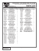
2005-2007 Corvette LS2 C6 (V-2) 2005 Part No. 4GS218-010SQ, 2006-2007 Part No. 4GS218-030SQ PARTS LIST ® ENGINEERING, LLC IMPORTANT: Before beginning installation, verify that all parts are included in the kit. Report any shortages or damaged parts immediately. Part No. Description Qty. 2E229-250 V2 T-TRIM, H/D, ASY 1 2A036-450 S/C PULLEY 4.50" 6-GROOVE 1 2A046-926 BELT, K060926-GATES 92.6" 6-RIB 1 4GS111-021 MTG BRKT ASY 1 2A017-375 SPACER, .
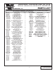
2005-2007 Corvette LS2 C6 (V-3) 2005 Part No. 4GS218-010L/-018L, 2006-2007 Part No. 4GS218-030L/-038L PARTS LIST ® ENGINEERING, LLC IMPORTANT: Before beginning installation, verify that all parts are included in the kit. Report any shortages or damaged parts immediately. Part No. Description 2F359-010 V3 T-TRIM, ASY 2A036-450 S/C PULLEY 4.50" 6-GROOVE 2A046-926 BELT, K060926-GATES 92.6" 6-RIB 4GS111-021 MTG BRKT ASY 2A017-375 SPACER, .
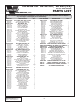
Corvette C6: '06-'08 LS7, '08 LS3 (V-2) Part No. 4GS218-020SQ PARTS LIST ® ENGINEERING, LLC IMPORTANT: Before beginning installation, verify that all parts are included in the kit. Report any shortages or damaged parts immediately. Part No.
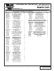
Corvette C6: '06-'08 LS7, '08 LS3 (V-3) Part No. 4GS218-020L/-028L PARTS LIST ® ENGINEERING, LLC IMPORTANT: Before beginning installation, verify that all parts are included in the kit. Report any shortages or damaged parts immediately. Part No.
1. PREPARATION/REMOVAL A. B. C. D. E. F G. Disconnect negative cable at the battery. Remove the air filter assembly and all ducting up to the throttle body. Remove Mass Air Flow (MAF) sensor from factory air inlet and set aside. Remove both of the coil/fuel rail covers on top of the engine and set aside. Remove the accessory drive belt. Remove the accessory drive belt spring tensioner. The belt and tensioner will not be reused.
2. HARMONIC DAMPER DOWEL PIN INSTALLATION NOTE: A. B. C. D. E. F. G. H. I. J. K. L. M. N. The purpose of this section is to provide access to the harmonic damper bolt area so that the crankshaft can be pinned to the damper to prevent the damper from spinning on the crank shaft. The following steps will work on all or most applications.
2. HARMONIC DAMPER DOWEL PIN INSTALLATION, cont’d. O. P. Q. R. S. T. 3. Install the supplied Ø1/4" x 1/2" long dowel pin into the drilled hole with the chamfered end pointed toward the front of the vehicle. Verify that the dowel pin is recessed slightly from the damper face. Install the supplied new damper retaining bolt as follows (If there are two bolts supplied, use the one that is the same length as the factory bolt): 1. Lightly coat the threads of the new retaining bolt with red threadlocker.
3. OIL DRAIN LINE INSTALLATION, cont’d (ENGINE OIL-FED KITS ONLY. APPLICATIONS WITH A V3 SUPERCHARGER SKIP AHEAD TO STEP 5) G. H. chips. Apply a small amount of silicone sealer to the new threads. Apply more sealer to the 3/8"NPT hose fitting and secure in hole. Make sure a seal is formed all around the fitting. Temporarily cover oil drain barb fitting to keep out debris. Drain the engine oil (if needed), install a new filter and refill with fresh oil 1-1/2" 1-1/2" Fig. 3-b (C6) 4.
5. RADIATOR ASSEMBLY RELOCATION A. B. C. D. 6. Z06 only (all others proceed with Step B): Remove the four screws securing the oil cooler to the forward radiator shroud. Remove the air temperature sensor from the passenger side of the radiator shroud (between the front bumper and the front of the radiator) and then remove the radiator shroud from the vehicle. Remove the four screws securing the radiator support cradle to the bottom of the frame rails. Place the four supplied .
7. SUPERCHARGER INSTALLATION *A. B. C. D. E. F. G. H. I. Attach the oil drain hose to the supercharger and secure with a clamp. Attach the supercharger mounting plate to the supercharger using 3/8-16 x 1-1/4" bolts w/washers in the location shown. (See Fig. 7-a.) Remove the evap. control mounted on the passenger side head to make room for the supercharger. Remove the metal bracket from the evap. control. Clean the front of the passenger’s side head of debris.
7. SUPERCHARGER INSTALLATION, cont’d. J. K. L. M. Install the supplied aluminum idler with the snap ring’s side facing the rear of the vehicle and the 3/8" thick spacer installed as shown using the supplied M10 thin-head bolt. (See Fig. 7-d.) Install the supplied spring tensioner and tensioner plate onto the mounting bracket as shown using a 3/8" x 2-1/4" bolt and washer. (See Fig. 7-e.) Index the tensioner so that it pilots in the middle hole on the tensioner plate.
7. SUPERCHARGER INSTALLATION, cont’d. O. Finish routing the belt around the supercharger and release the spring tensioner. The belt may be very tight. In this case it may be necessary to have one person retract the tensioner and have another partially install the belt on the supercharger pulley. NOTE: The pilot hole from the tensioner may require adjustment during belt fitment. P. *Q.
8. CHARGE AIR COOLER INSTALLATION A. B. C. D. E. F. G. Remove the passenger’s side inner fender liner from in front of the wheel. Remove the horn assembly and re-attach in the location shown in Fig. 8-a using the supplied 10-24 hardware. Bend the horn bracket so that the horns are horizontal, will not fill with water and do not contact anything. Test the horns. If they are not working properly, bend the bracket until they are not touching anything. Remove the radiator shroud in front of the radiator.
9. INLET DUCT INSTALLATION A. B. C. D. E. Bend the radiator side-plate as shown. (See Fig. 9-a.) Attach the inlet duct to the supercharger inlet using the supplied Ø3.75" sleeve and #60 clamps. Install the supplied 3/8" elbow in the hole in the end of the air filter. Install the air filter onto the duct inlet. LS2-Connect supplied 3/8" hose from the elbow installed in the air filter to the passenger’s side valve cover breather hose barb using the supplied 3/8" hose.
10. RADIATOR SHROUD INSTALLATION A. B. C. D E. F. Z06 vehicles, install the supplied bracket onto the passenger’s side CAC studs so that it lines up with the oil cooler. Use the original hardware to secure the oil cooler. (See Fig. 10-c.) Install the lower side panel onto the driver’s side studs. (See Fig. 10-b.) For ZO6 vehicles, use the original hardware to go through the panel and support the oil cooler. (See Fig. 10-d.
10. RADIATOR SHROUD INSTALLATION, cont’d. G. H. Attach the lower part of each panel to the studs on the charge cooler and secure with the supplied nuts and washers. (See Fig. 10-g.) Install the supplied weather strip around the upper edge of the radiator shroud to seal it to the hood. (See Fig. 10-h.) Fig. 10-e (Air Temp Sensor) SUPPLIED 10-24 HARDWARE ORIGINAL HARDWARE SUPPLIED 5/16" NUTS & WASHERS Fig. 10g Fig. 10-f SUPPLIED WEATHERSTRIP Fig.
11. DISCHARGE DUCT INSTALLATION A. B. Remove the two screws securing the power steering cooler (if equipped). Rotate the power steering cooler so that the passenger’s side is pointed upwards towards the supercharger. Re-install the driver’s side screw and secure the passenger’s side with zip-ties. Install a 2.75" sleeve on the supercharger discharge duct and secure with a #44 hose clamp. From underneath the vehicle, install the duct onto the supercharger discharge. BYPASS VALVE S/C DISCHARGE DUCT Fig.
11. DISCHARGE DUCT INSTALLATION, cont’d. C. D. E. F. G. H. I. J. K. L. M. Install the CAC inlet tube using a 2-3/4" to 3" reducer sleeve on the CAC and a 55° elbow to attach it to the supercharger discharge duct. Tighten clamps on all connections. Install the bypass valve onto the supercharger discharge duct using the supplied gasket and hardware. (See Fig. 11-a.) Re-install inner fender liner and cut as required to make clearance for the CAC inlet duct. (See Fig.
12. FUEL INJECTOR REPLACEMENT A. B. C. D. E. F. G. H. I. J. K. L. Relieve the fuel system pressure Disconnect the eight fuel injector electrical plugs. Remove the four screws that hold down the fuel rail on the intake manifold. Lift up on the rails evenly and remove all eight injectors. Remove the lower O-ring from each of the supplied injectors and set aside. They will not be re-used. Replace the lower O-ring on the supplied injectors with the supplied O-ring.
13. REFLASH COMPUTER IMPORTANT! To ensure trouble-free programming of your vehicle's computer: • Make sure the vehicle's battery is sufficiently charged. • Turn off all accessories and close doors to prevent unnecessary drain on the battery. • Do not attempt to program your vehicle while a battery charger is connected. • Improper battery voltage will result in failure of the programming process. • Do not disconnect the cable or turn off the ignition during programming. A. B. C. D. E. F. G. H. I.
14. FINAL ASSEMBLY AND CHECK A. B. C. D. E. F. If your vehicle has gone over 20,000 miles since its last spark plug change, it is a good idea to change the spark plugs now, before test-driving. Make sure that oil drain to oil pan fitting is tight and that the engine is filled with factory specified oil. Make sure radiator and overflow tank are filled with 50/50 coolant/water mix. Make sure that the vehicle is filled with 91 octane or higher fuel before commencing a test drive.
® ENGINEERING, LLC 1650 PACIFIC AVENUE • CHANNEL ISLANDS, CA 93033-9901 • (805) 247-0226 FAX (805) 247-0669 • www.vortechsuperchargers.com • M-F 8:00 AM - 4:30 PM PST P/N: 4GS020-010 ©2009 Vortech Engineering, LLC All Rights Reserved, Intl. Copr. Secured 12MAY09 v3.1 05-08Corvette(4GSv3.