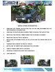
CHEVY IMPALA 1992 - 1996 LSD INSTALLATION 50061011 Chevy Impala SS A Division of KW automotive North America, Inc 1
50061011 Chevy Impala SS A Division of KW automotive North America, Inc 2
INSTALLATION INTRODUCTION 1. REMOVING THE FENDER, DOORS FROM THE A-PILLAR AND DISCONNECTING THE WIRE HARNESS @ THE DOOR JAM 2. REMOVING THE EXISTING DOOR HINGES FROM THE DOORS; TOP AND BOTTOM. 3. MODIFYING THE INTERNAL FENDER AREAS FOR THE HINGE CLEARANCE. 4. MODIFYING THE ELECTRICAL HARNESS. 5. INSTALLING THE GROUND PLATE TO THE A-PILLAR AND THE SWING ARM TO THE DOOR. 6. HANGING AND ALIGNING THE VEHICLE DOORS. 7. INSTALLING THE FENDER AND CHECKING FOR CLEARANCE. 8.
Installation Instructions LamboStyleDoors (The instructions are to be used as a reference only. Please repeat steps for both doors.
DANGER WARNINGS LSD Doors must be installed according to the provided vehicle specific instructions from LSD Doors and installation should be performed by an authorized dealer. Always follow the latest accident prevention regulations (not applicable for North America) for each step to prevent any serious bodily harm or injury. Extending the factory wire harness must be completed according to the vehicle manufacturer‘s guidelines for cable repairs.
! Attention notice: An additional inside support handle must be installed to solve the issue of possible difficulty of griping the door, when raising and lowering your door from your seated position. If there are white lights on your door, these must be made ineffective, e. g. taking of the bulb and bulb holder according to fig. 5.22 ECE-law no. 48. After mounting the LSD hinge system you must reinstall your OEM inner fender covers to keep your LSD hinges free from debris and corrosion.
General Lubrication Information In order for the LSD Door System to function properly, adequate lubrication is essential at all pivot points on the system. Periodic lubricating of all pivot points is highly recommended on a consistent basis. This helps in the life of all bearings involved.
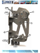
HARDWARE LIST ( per vehicle side) 1x A 5X B 1x C 3x D Snap ring Cable ties Gas Damper 2450 M.A.R.
OEM C F OEM C A E A OEM C OEM 50061011 Chevy Impala SS A Division of KW automotive North America, Inc 9
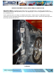
ORIGINAL EQUIPMENT CHASSIS HINGE REMOVAL MODIFICATION IMPORTANT NOTE: The following instructions given, in sequential order, is a step-by-step procedure to minimize any installation difficulty that may occur. By skipping steps, un-necessary problems can arise during the installation process. On this particular vehicle, the hinges are bolted to the A-Pillar. Using a wrench, un-bolt both the two top mount bolts and the two bottom bolts that attach the hinge/door to the A-Pillar.
STEP 1 INNER FENDER MODIFICATION For this particular application, once the outer fender has been removed, the inner fender needs to be modified, to accommodate the new LSD hinges.
STEP 1 INNER FENDER MODIFICATION –cont’dFor this particular application, once the outer fender has been removed, the inner fender needs to be modified, to accommodate the new LSD hinges. The following pictures show the areas (outlined in white) that will need to be removed. 1a. Using a cutting tool, a manual or pneumatic saw, begin cutting along the white line to wards the top of the inner fender (Photo 1). Cut-out completely and remove (Photo 2). 1b.
STEP 1 INNER FENDER MODIFICATION –cont’dFor this particular application, once the outer fender has been removed, the inner fender needs to be modified, to accommodate the new LSD hinges. The following pictures show the areas (outlined in white) that will need to be removed. 1c. The secondary cut for the removal of the large inner fender lip is done the same way as the first. With this area already outlined, begin cutting the lines you have marked (Photo 3). 1d.
STEP 2 INNER FENDER MODIFICATION –cont’dFor this particular application also, the outer fender also needs to be modified, to accommodate the new LSD hinges. The following pictures show the areas (outlined in white) that will need to be removed. 2a. This cut for the removal of the fender lip is done using a cutting tool. Outline the area using the dimensions given to you. This (Photo 5) shows the before cut. 2b. The final look of the area (Photo 6) is shown. PHOTO 5 2cm 5mm-7mm 3.5cm 7.5mm 22cm 23.
STEP 3 DIS-ASSEMBLING THE SWING ARM FROM THE GROUND PLATE 3a. Your new LSD Door Hinges have come assembled. 3b. As identified in (Photo 8), disassemble the swing arm from the ground plate. Un-bolt all four mounting bolts or allen-heads and remove completely.
STEP 4 MOUNTING THE GROUND PLATE TO THE A-PILLAR 4a. Using the kit supplied mounting hardware for the Ground Plate, attach it to the A-Pillar. Finger tight initially, then using a wrench, torque to specifications. The photos below show the top and bottom mounting points of the Ground Plate. BOTTOM MOUNT 4b. TOP MOUNT For this particular application, there is an additional mount point that stiffens the top of the Ground Plate, giving the Ground Plate more rigidity.
STEP 5 MODIFYING THE CHASSIS WIRING HARNESS IMPORTANT NOTE: Prior to beginning extending the wiring harness from the A-pillar, each individual wire needs to be cut one at a time. Each wire that is cut, has to be staggered (See 5g) from the previous cut wire. By doing this, you will eliminate, when wrapping all the wires, one large taped ball. 5a. If the wiring harness comes equipped with an insulation cover, this will need to be removed.
STEP 5 MODIFYING THE CHASSIS WIRING HARNESS –cont’d5g. VERY IMPORTANT: 5h. Remember to stagger the cuts for each individual wire. This will eliminate having a large wrap and will allow for minimal size and maximum flexibility. 5i. In the photo below an (INCORRECT) version is shown. By cutting it this way, wrapping the wire at the end, will create a large ball in the middle of the newly extended wire harness. Wire harness flexibility would be minimal. 5j.
STEP 5 ROUTING THE WIRE HARNESS IMPORTANT NOTE: 5n.
STEP 6 MOUNTING THE LSD SWING ARM 6a. Using the existing O.E.M. nuts, mount the LSD swing arm on the door, matching up each respective mount hole. Two mount holes at the top and two at the bottom (Photo 15). Locate the mounting nuts at the center of their respective mount holes. 6b. Using a wrench, torque the bolts to 20ft-lb.
STEP 7 MOUNTING THE DOOR TO THE A-FRAME IMPORTANT NOTE: THIS STEP SHOULD BE DONE WITHOUT THE GAS SPRING INSTALLED 7a. Place the door back on the vehicle and close the door completely. 7a. Install the MAGICSTIK into position (Photo 16) Initially, this is done for mounting purposes only, using the MAGICSTIK as a guide. 7b. Lifting the door into position, guide the MAGICSTIK into its mating block (Photo 17), manually holding the door there, as close to the closed position as possible. 7c.
STEP 8 MOUNTING THE GAS DAMPER (after correct gap distance has been established) IMPORTANT NOTE: • PRIOR TO MOUNTING THE GAS DAMPER AT ITS RESPECTIVE MOUNTING POINTS, WE HIGHLY RECOMMEND USING AN ANTI-RUST LUBRICANT, WIPING DOWN THE MOUNT POINTS TO PREVENT RUSTING.
STEP 8 MOUNTING THE GAS DAMPER (after correct gap distance has been established) 8a. Hang (mount) the gas damper on the mount point of the swing arm (Photo 22). Secure it with the kit supplied security ring, by using needle-nose pliers. 8b. NOTE: Use care when installing the security ring. 8c. The rubber o-ring, located on top of the gas damper has to be moved (Photo 23) between the Ground plate and the top of the ball joint of the gas damper (Photo 24). PHOTO 22 8d.
STEP 9 FINAL DOOR ADJUSTMENT… IF REQUIRED 9a. With the gas spring installed 9b. At this point of the installation, open and close the door slowly. Check and see if the Magic Stick aligns correctly to the Magic Stick receptacle. If adjustment is necessary, adjust the Magic Stick receptacle to align with the Magic Stick (Photo 20). In some instances the Magic Stick receptacle has maxed out on adjustment.
IF REQUIRED 9d. With the gas spring uninstalled. 9e. If spacer (s) installation is needed, install one at a time, starting at the top, (Photo 21) working your way to the bottom, to see if that particular spacer aligns the door correctly. Begin at the top mounts, STEP 1A to STEP 1B, etc, etc. 2 L L 2 STEP 1A - TOP STEP 2A - BOTTOM L L 2 2 STEP 1B - TOP STEP 2B - BOTTOM PHOTO 21 Re install gas spring and check door alignment again. Repeat if necessary.
STEP 10 ROUTING THE WIRE HARNESS 10a. Pivot the door carefully up and make sure there is sufficient clearance on the fender, Apillar and hood. If necessary, adjust the Ground plate or the LSD swing arm again. 10b. Lay the wire harness on and attach it to the marked points shown (Photo 26). Secure the wire harness with the kit supplied cable ties.
11. ROLLER ADJUSTMENT NOTE: The door needs to be in the closed position for this adjustment to be properly done. 11a. Please adjust the slide roller so the LSD swing arm has the initial contact and preload while opening and closing of the door. (Photo 27). 11b. To get the adjustment of the slide roller, we have designed an horizontal and vertical adjustment to the slide roller mount. IMPORTANT NOTE: 11c.
COMMON TROUBLESHOOTING QUESTIONS and ANSWERS Q1: WHY DOES THE BOTTOM OF THE DOOR NOT SIT FLUSH, AT THE FRONT OR REAR?: A1: LSD door hinges are engineered and designed to compensate for this issue. They are designed to be installed in the center location of all mounting slots. Some vehicles are different however; adjusting the location of the swing arm mounts on the door will fix this problem.
50061011 Chevy Impala SS A Division of KW automotive North America, Inc 29
50061011 Chevy Impala SS A Division of KW automotive North America, Inc 30
50061011 Chevy Impala SS A Division of KW automotive North America, Inc 31
50061011 Chevy Impala SS A Division of KW automotive North America, Inc 32
50061011 Chevy Impala SS A Division of KW automotive North America, Inc 33