2004 Chevrolet Venture Owner Manual Seats and Restraint Systems ........................... 1-1 Front Seats ............................................... 1-3 Rear Seats ............................................... 1-6 Safety Belts ............................................. 1-27 Child Restraints ....................................... 1-53 Air Bag Systems ...................................... 1-92 Restraint System Check .......................... 1-102 Features and Controls .........................
Canadian Owners A French language copy of this manual can be obtained from your dealer or from: Helm, Incorporated P.O. Box 07130 Detroit, MI 48207 GENERAL MOTORS, GM, the GM Emblem, CHEVROLET, the CHEVROLET Emblem and the name VENTURE are registered trademarks of General Motors Corporation. This manual includes the latest information at the time it was printed. We reserve the right to make changes after that time without further notice.
Safety Warnings and Symbols You will find a number of safety cautions in this book. We use a box and the word CAUTION to tell you about things that could hurt you if you were to ignore the warning. {CAUTION: In the caution area, we tell you what the hazard is. Then we tell you what to do to help avoid or reduce the hazard. Please read these cautions. If you don’t, you or others could be hurt. You will also find a circle with a slash through it in this book.
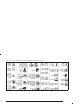
Vehicle Damage Warnings Vehicle Symbols Also, in this manual you will find these notices: The vehicle has components and labels that use symbols instead of text. Symbols are shown along with the text describing the operation or information relating to a specific component, control, message, gage, or indicator. Notice: These mean there is something that could damage your vehicle. A notice tells about something that can damage your vehicle.
These are some examples of symbols that may be found on the vehicle: v
✍ NOTES vi
Section 1 Seats and Restraint Systems Front Seats ......................................................1-3 Manual Seats ................................................1-3 Six-Way Power Seats .....................................1-4 Reclining Seatbacks ........................................1-4 Head Restraints .............................................1-6 Rear Seats .......................................................1-6 Rear Seat Operation .......................................
Section 1 Seats and Restraint Systems Air Bag Systems ............................................1-92 Where Are the Air Bags? ...............................1-95 When Should an Air Bag Inflate? ....................1-98 What Makes an Air Bag Inflate? .....................1-99 How Does an Air Bag Restrain? .....................1-99 What Will You See After an Air Bag Inflates? .....1-100 Servicing Your Air Bag-Equipped Vehicle ........1-102 1-2 Restraint System Check ................................
Front Seats {CAUTION: Manual Seats Use the lever located on the front of the seat to adjust the seat forward or rearward. Pull up the lever to unlock the seat. Slide the seat to where you want it and release the lever. You can lose control of the vehicle if you try to adjust a manual driver’s seat while the vehicle is moving. The sudden movement could startle and confuse you, or make you push a pedal when you do not want to. Adjust the driver’s seat only when the vehicle is not moving.
Six-Way Power Seats Reclining Seatbacks Your vehicle may have this feature. If it does, the six-way power seat control is located on the outboard sides of the driver’s and front passenger’s seats. • Move the front of the control up or down to adjust the front portion of the cushion up or down. • Move the rear of the control up or down to adjust the rear portion of the cushion up or down. • Lift up or push down on the whole control to move the entire seat up or down.
{CAUTION: Sitting in a reclined position when your vehicle is in motion can be dangerous. Even if you buckle up, your safety belts can not do their job when you are reclined like this. The shoulder belt can not do its job because it will not be against your body. Instead, it will be in front of you. In a crash you could go into it, receiving neck or other injuries. But don’t have a seatback reclined if your vehicle is moving. The lap belt can not do its job either.
Head Restraints Rear Seats Rear Seat Operation The rear seats in your vehicle have levers and straps used to adjust, remove, and reinstall the seats. By using the levers and straps in the correct order, you can easily remove the seats from the vehicle. When you put the seats back in the vehicle, follow the label on the back of the seat for proper location. Second Row Safety Belt Stowage Adjust your head restraint so that the top of the restraint is closest to the top of your head.
Flip and Fold Feature The rear seats in your vehicle can be folded forward. Use this feature for exiting and entering third row seats. 1. If the seats have the adjustable head restraints, push them fully down. 2. Fold the seatback flat on the seat, by either pulling on the nylon strap on the rear of the seat or lifting up on the lever located on the front of the seatback. If the seat adjusts, slide it all the way back. To return the seat(s) to the normal position, do the following: 1.
Split Bench Seats If you have the split bench seat (50/50 or 40/60), the seatbacks can be folded forward or reclined individually and the seats can be removed individually. The second row (40/60) sections can also be adjusted forward or rearward individually. The second row (40/60) split bench may be equipped with a built-in child restraint. See Built-In Child Restraint on page 1-81. Adjusting the Split Bench Seats (Second Row) The second row bench seats are adjustable.
The other lever is located on the rear of the seat. The seatbacks on each section of the split bench seat can be either folded forward or reclined. The following explains how to use the nylon strap or recliner lever to fold or recline the seatbacks. Lift up either lever and slide the seat forward or rearward. Release the lever. Push and pull on the seat to make sure it is locked into place.
To recline the seatback, pull the nylon strap or lift the recliner lever. Press back on the seatback until you reach the desired position then let go of the strap or lever. To return the seatback to an upright position, pull on the nylon strap or lift the recliner lever without putting any pressure on the seatback. Push and pull on the seatback to be sure it is locked into place. 2. Push the red center of the buckle with a small pointed object to remove the seat belt, if needed.
5. From behind the bench seat, pull the nylon strap at the center of the base of the seat to release the rear latches from the floor pins. Do not let go of the strap until the seat is folded all the way forward. 6. To unlatch the front latches, squeeze the angled bar toward the straight crossbar. 7. Remove the seat by rocking it slightly forward, then toward the rear of the vehicle and then pulling it out. Repeat these steps for the other section of the split bench seat.
Replacing the Split Bench Seats {CAUTION: {CAUTION: If the seatback is not locked, it could move forward in a sudden stop or crash. That could cause injury to the person sitting there. Always press rearward on the seatback to be sure it is locked. {CAUTION: A seat that isn’t locked into place properly can move around in a collision or sudden stop. People in the vehicle could be injured. Be sure to lock the seat into place properly when installing it.
2. Make sure the bench seat is angled so that the front hooks clear the floor pins. If the front legs are not attached correctly, the rear legs will not attach to the rear set of floor pins. 1. Squeeze the angled bar toward the solid crossbar while placing the front hooks of the bench seat onto the front two floor pins.
If the front latches are not attaching correctly, check that the seat is in the full rear position. 3. Firmly push the rear hooks onto the rear floor pins by pushing down on the rear of the seat. 4. Try to raise the seat to check that it is locked down. 5. Lift the seatback recliner lever or pull the nylon strap on the back of the seat and raise the seatback until it locks upright. 6. Push and pull on the seatback to check that it is locked.
The other lever is located on the rear of the bucket seat. The seatback on a bucket seat can be either folded forward or reclined. The following explains how to use either the nylon strap or the lever to fold or recline the seatback. Lift up either lever and slide the seat forward or rearward. Release the lever. Push and pull on the seat to make sure it is locked into place. Folding or Reclining the Seatbacks {CAUTION: If the seatback is not locked, it could move forward in a sudden stop or crash.
To recline the seatback, pull the nylon strap or lift the recliner lever. Press back on the seatback until you reach the desired position, then let go of the strap or lever. To return the seatback to an upright position, pull on the nylon strap or lift the recliner lever without putting any pressure on the seatback. Push and pull on the seatback to be sure it is locked into place. Removing the Bucket Seats Make sure the seatback is in the upright position. The head restraints should be fully down. 1.
You can also lift the lever on the side of the seat to release the rear latches from the floor pins. Do not let go of the strap or lever until the seat is folded all the way forward. 4. To unlatch the front latches, with the seat folded forward, squeeze the angled bar toward the straight crossbar. 5. Remove the seat by rocking it slightly forward, then toward the rear of the vehicle and then pulling it out. This should be done in one motion.
Replacing the Bucket Seats {CAUTION: {CAUTION: If the seatback is not locked, it could move forward in a sudden stop or crash. That could cause injury to the person sitting there. Always press rearward on the seatback to be sure it is locked. {CAUTION: A seat that isn’t locked into place properly can move around in a collision or sudden stop. People in the vehicle could be injured. Be sure to lock the seat into place properly when installing it.
2. Make sure the bucket seat is angled so that the front hooks clear the floor pins. If the front legs are not attached correctly, the rear legs will not attach to the rear set of floor pins. If the front latches are not attaching correctly, check that the seat is in the full rear position. 3. Firmly push the rear hooks onto the rear floor pins by pushing down the rear of the seat. 4. Try to raise the seat to check that it is locked down. 5.
Captain Chairs If your vehicle has captain’s chairs, the chairs and seatbacks can be adjusted forward or rearward. Adjusting the Captain’s Chairs (Second Row) The second row captain’s chairs can be adjusted forward or rearward. There are two adjustment levers on each seat. One is located below the center, in front of the seat. The other is located across the rear of the seat. Lift up either lever to slide the seat forward or rearward. Release the lever.
Removing the Captain’s Chairs 2. The seat can then be lifted off the front floor pins and removed from the vehicle. 1. Pull the nylon strap behind the chair to release the rear hooks from the floor pins.
Replacing the Captain’s Chairs {CAUTION: {CAUTION: If the seatback is not locked, it could move forward in a sudden stop or crash. That could cause injury to the person sitting there. Always press rearward on the seatback to be sure it is locked. A safety belt that is improperly routed, not properly attached, or twisted won’t provide the protection needed in a crash. The person wearing the belt could be seriously injured.
1. Hook the front latches over the front floor pins. 2. Push the rear of the seat down to lock the rear latches onto the rear set of floor pins. 3. Push and pull on the seat to be sure it is properly attached.
Stowable Seat Your vehicle may have a stowable seat. The stowable seat is a full bench seat and comes with the convenience center. See Convenience Center on page 2-59 for more information. The stowable seat can be removed and replaced, or with the seatback folded, it can lie flush with the convenience center. To fold down the seatback, pull up on the lever located on the back of the seat, and push the seatback down until it is locked into place.
To raise the seatback, do one of the following: • From the rear of the vehicle, pull up on the lever to release the seatback, then pull the strap located on the right side of the seat, to pull the seatback up. The seatback has a patch of hook and loop fastener to stow the strap on the rear of the seat when not in use. • From the passenger’s side sliding door, pull up on the lever to release the seatback, then push up on the seatback to raise the seat.
Replacing the Stowable Seat {CAUTION: {CAUTION: If the seatback is not locked, it could move forward in a sudden stop or crash. That could cause injury to the person sitting there. Always press rearward on the seatback to be sure it is locked. A safety belt that is improperly routed, not properly attached, or twisted won’t provide the protection needed in a crash. The person wearing the belt could be seriously injured.
The seat must be placed in the proper location for the legs to attach correctly. Make sure the seat is in its upright position before beginning this procedure. 1. Place the front hooks of the seat onto the front floor pins in the third row. To do this, the seat will need to be angled so the front hooks clear the floor pins. If the front legs are not attached correctly, the rear legs will not attach to the rear set of floor pins. 2.
Your vehicle has a light that comes on as a reminder to buckle up. See Safety Belt Reminder Light on page 3-41. Why Safety Belts Work When you ride in or on anything, you go as fast as it goes. In most states and in all Canadian provinces, the law says to wear safety belts. Here’s why: They work. You never know if you’ll be in a crash. If you do have a crash, you don’t know if it will be a bad one. A few crashes are mild, and some crashes can be so serious that even buckled up a person wouldn’t survive.
Put someone on it. Get it up to speed. Then stop the vehicle. The rider doesn’t stop.
The person keeps going until stopped by something. In a real vehicle, it could be the windshield... 1-30 or the instrument panel...
Questions and Answers About Safety Belts Q: Won’t I be trapped in the vehicle after an accident if I’m wearing a safety belt? A: You could be – whether you’re wearing a safety belt or not. But you can unbuckle a safety belt, even if you’re upside down. And your chance of being conscious during and after an accident, so you can unbuckle and get out, is much greater if you are belted.
Q: If I’m a good driver, and I never drive far from home, why should I wear safety belts? A: You may be an excellent driver, but if you’re in an accident – even one that isn’t your fault – you and your passengers can be hurt. Being a good driver doesn’t protect you from things beyond your control, such as bad drivers. Most accidents occur within 25 miles (40 km) of home. And the greatest number of serious injuries and deaths occur at speeds of less than 40 mph (65 km/h). Safety belts are for everyone.
3. Pick up the latch plate and pull the belt across you. Don’t let it get twisted. The shoulder belt may lock if you pull the belt across you very quickly. If this happens, let the belt go back slightly to unlock it. Then pull the belt across you more slowly. 4. Push the latch plate into the buckle until it clicks. Pull up on the latch plate to make sure it is secure. If the belt isn’t long enough, see Safety Belt Extender on page 1-52.
The lap part of the belt should be worn low and snug on the hips, just touching the thighs. In a crash, this applies force to the strong pelvic bones. And you’d be less likely to slide under the lap belt. If you slid under it, the belt would apply force at your abdomen. This could cause serious or even fatal injuries. The shoulder belt should go over the shoulder and across the chest. These parts of the body are best able to take belt restraining forces.
Shoulder Belt Height Adjuster Before you begin to drive, move the shoulder belt adjuster to the height that is right for you. To move it down, push down on the button and move the height adjuster to the desired position. You can move the adjuster up just by pushing up on the shoulder belt guide. After you move the adjuster to where you want it, try to move it down without pushing the button down to make sure it has locked into position.
Q: What’s wrong with this? {CAUTION: You can be seriously hurt if your shoulder belt is too loose. In a crash, you would move forward too much, which could increase injury. The shoulder belt should fit against your body. A: The shoulder belt is too loose. It won’t give nearly as much protection this way.
Q: What’s wrong with this? {CAUTION: You can be seriously injured if your belt is buckled in the wrong place like this. In a crash, the belt would go up over your abdomen. The belt forces would be there, not at the pelvic bones. This could cause serious internal injuries. Always buckle your belt into the buckle nearest you. A: The belt is buckled in the wrong place.
Q: What’s wrong with this? {CAUTION: You can be seriously injured if your belt goes over an armrest like this. The belt would be much too high. In a crash, you can slide under the belt. The belt force would then be applied at the abdomen, not at the pelvic bones, and that could cause serious or fatal injuries. Be sure the belt goes under the armrests. A: The belt is over an armrest.
Q: What’s wrong with this? {CAUTION: You can be seriously injured if you wear the shoulder belt under your arm. In a crash, your body would move too far forward, which would increase the chance of head and neck injury. Also, the belt would apply too much force to the ribs, which are not as strong as shoulder bones. You could also severely injure internal organs like your liver or spleen. A: The shoulder belt is worn under the arm. It should be worn over the shoulder at all times.
Q: What’s wrong with this? {CAUTION: You can be seriously injured by a twisted belt. In a crash, you would not have the full width of the belt to spread impact forces. If a belt is twisted, make it straight so it can work properly, or ask your dealer to fix it. A: The belt is twisted across the body.
To unlatch the belt, just push the button on the buckle. The belt should go back out of the way. Before you close the door, be sure the belt is out of the way. If you slam the door on it, you can damage both the belt and your vehicle.
Safety Belt Use During Pregnancy Safety belts work for everyone, including pregnant women. Like all occupants, they are more likely to be seriously injured if they don’t wear safety belts. The best way to protect the fetus is to protect the mother. When a safety belt is worn properly, it’s more likely that the fetus won’t be hurt in a crash. For pregnant women, as for anyone, the key to making safety belts effective is wearing them properly.
Center Passenger Position (Bucket Seat) Lap Belt If your vehicle has bucket seats, someone can sit in the center position bucket seat. When you sit in the center position bucket seat, you have a lap safety belt which has a retractor. 1. Pick up the latch plate and, in a single motion, pull the belt across you. Don’t let it get twisted.
2. Push the latch plate into the buckle until it clicks. If the belt stops before it reaches the buckle, let it go back all the way and start again. Pull up on the latch plate to make sure it is secure. 3. Feed the lap belt into the retractor to tighten it. 4. Position and release it the same way as the lap part of a lap-shoulder belt. If the belt isn’t long enough, see Safety Belt Extender on page 1-52.
Lap Belt If your vehicle has a third row rear bench seat, someone can sit in the center position. To make the belt shorter, pull its free end as shown until the belt is snug. When you sit in the center position of the bench seat, you have a lap safety belt, which has no retractor. To make the belt longer, tilt the latch plate and pull it along the belt. Buckle, position and release it the same way as the lap part of a lap-shoulder belt.
Rear Seat Passengers Rear Seat Outside Passenger Positions It’s very important for rear seat passengers to buckle up! Accident statistics show that unbelted people in the rear seat are hurt more often in crashes than those who are wearing safety belts. Rear passengers who aren’t safety belted can be thrown out of the vehicle in a crash. And they can strike others in the vehicle who are wearing safety belts. Lap-Shoulder Belt The positions next to the windows have lap-shoulder belts.
1. Pick up the latch plate and pull the belt across you. Don’t let it get twisted. The shoulder belt may lock if you pull the belt across you very quickly. If this happens, let the belt go back slightly to unlock it. Then pull the belt across you more slowly. 2. Push the latch plate into the buckle until it clicks. In the third row, if the belt stops before it reaches the buckle, tilt the latch plate and keep pulling until you can buckle it.
Third Row Outside Passenger Position Pull up on the latch plate to make sure it is secure. When the shoulder belt is pulled out all the way, it will lock. If it does, let it go back all the way and start again. If the belt is not long enough, see Safety Belt Extender on page 1-52. Make sure the release button on the buckle is positioned so you would be able to unbuckle the safety belt quickly if you ever had to. 1-48 3.
{CAUTION: You can be seriously hurt if your shoulder belt is too loose. In a crash, you would move forward too much, which could increase injury. The shoulder belt should fit against your body. The lap part of the belt should be worn low and snug on the hips, just touching the thighs. In a crash this applies force to the strong pelvic bones. And you’d be less likely to slide under the lap belt. If you slid under it, the belt would apply force at your abdomen.
Rear Safety Belt Comfort Guides for Children and Small Adults Rear safety belt comfort guides will provide added safety belt comfort for older children who have outgrown booster seats and for small adults. When installed on a shoulder belt, the comfort guide better positions the belt away from the neck and head. If your vehicle has bucket seats in the second row, there is one guide for each outside passenger position.
2. Place the guide over the belt and insert the two edges of the belt into the slots of the guide. 3. Be sure that the belt is not twisted and it lies flat. The guide must be on top of the belt.
Safety Belt Pretensioners Your vehicle has safety belt pretensioners. You’ll find them on the buckle end of the safety belts for the driver and right front passenger. They help the safety belts reduce a person’s forward movement in a moderate to severe crash in which the front of the vehicle hits something. Pretensioners work only once. If they activate in a crash, you’ll need to get new ones, and probably other new parts for your safety belt system.
Child Restraints Older Children Q: What is the proper way to wear safety belts? A: If possible, an older child should wear a lap-shoulder belt and get the additional restraint a shoulder belt can provide. The shoulder belt should not cross the face or neck. The lap belt should fit snugly below the hips, just touching the top of the thighs. It should never be worn over the abdomen, which could cause severe or even fatal internal injuries in a crash.
{CAUTION: Never do this. Here two children are wearing the same belt. The belt can not properly spread the impact forces. In a crash, the two children can be crushed together and seriously injured. A belt must be used by only one person at a time.
{CAUTION: Never do this. Here a child is sitting in a seat that has a lap-shoulder belt, but the shoulder part is behind the child. If the child wears the belt in this way, in a crash the child might slide under the belt. The belt’s force would then be applied right on the child’s abdomen. That could cause serious or fatal injuries. Wherever the child sits, the lap portion of the belt should be worn low and snug on the hips, just touching the child’s thighs.
Infants and Young Children Everyone in a vehicle needs protection! This includes infants and all other children. Neither the distance traveled nor the age and size of the traveler changes the need, for everyone, to use safety restraints. In fact, the law in every state in the United States and in every Canadian province says children up to some age must be restrained while in a vehicle.
{CAUTION: People should never hold a baby in their arms while riding in a vehicle. A baby does not weigh much — until a crash. During a crash a baby will become so heavy it is not possible to hold it. For example, in a crash at only 25 mph (40 km/h), a 12-lb. (5.5 kg) baby will suddenly become a 240-lb. (110 kg) force on a person’s arms. A baby should be secured in an appropriate restraint.
Q: What are the different types of add-on child {CAUTION: restraints? A: Add-on child restraints, which are purchased by the Children who are up against, or very close to, any air bag when it inflates can be seriously injured or killed. Air bags plus lap-shoulder belts offer outstanding protection for adults and older children, but not for young children and infants. Neither the vehicle’s safety belt system nor its air bag system is designed for them.
{CAUTION: {CAUTION: Newborn infants need complete support, including support for the head and neck. This is necessary because a newborn infant’s neck is weak and its head weighs so much compared with the rest of its body. In a crash, an infant in a rear-facing seat settles into the restraint, so the crash forces can be distributed across the strongest part of an infant’s body, the back and shoulders. Infants always should be secured in appropriate infant restraints.
Child Restraint Systems An infant car bed (A), a special bed made for use in a motor vehicle, is an infant restraint system designed to restrain or position a child on a continuous flat surface. Make sure that the infant’s head rests toward the center of the vehicle. 1-60 A rear-facing infant seat (B) provides restraint with the seating surface against the back of the infant. The harness system holds the infant in place and, in a crash, acts to keep the infant positioned in the restraint.
A forward-facing child seat (C-E) provides restraint for the child’s body with the harness and also sometimes with surfaces such as T-shaped or shelf-like shields. A booster seat (F-G) is a child restraint designed to improve the fit of the vehicle’s safety belt system. Some booster seats have a shoulder belt positioner, and some high-back booster seats have a five-point harness. A booster seat can also help a child to see out the window.
Q: How do child restraints work? A: A child restraint system is any device designed for use in a motor vehicle to restrain, seat, or position children. A built-in child restraint system is a permanent part of the motor vehicle. An add-on child restraint system is a portable one, which is purchased by the vehicle’s owner. For many years, add-on child restraints have used the adult belt system in the vehicle. To help reduce the chance of injury, the child also has to be secured within the restraint.
Where to Put the Restraint Accident statistics show that children are safer if they are restrained in the rear rather than the front seat. We, therefore, recommend that child restraints be secured in a rear seat, including an infant riding in a rear-facing infant seat, a child riding in a forward-facing child seat and an older child riding in a booster seat. Never put a rear-facing child restraint in the front passenger seat.
Top Strap Some child restraints have a top strap, or “top tether.” It can help restrain the child restraint during a collision. For it to work, a top strap must be properly anchored to the vehicle. Some top strap-equipped child restraints are designed for use with or without the top strap being anchored. Others require the top strap always to be anchored. Be sure to read and follow the instructions for your child restraint.
Don’t use a child restraint that requires a top strap in the right front passenger’s position because there’s no place to anchor the top strap. Top Strap Anchor Location Anchor the top strap to one of the following anchor points. Be sure to use an anchor point located on the same side of the vehicle as the seating position where the child restraint will be placed. If you have an adjustable head restraint, route the top strap under it.
Third Row Third Row (Stowable Seat) An anchor bar for a top strap is located at the rear of the seat cushion for each second and third row outboard seating position, and for the center position of the second row. The anchor bar for the stowable bench seat is located on the passenger’s side of the crossbar. Use the center seating position to use the anchor bar properly. If the convenience center is in the vehicle, you must lift the tray sill to use the anchor.
Lower Anchorages and Top Tethers for Children (LATCH System) This system, designed to make installation of child restraints easier, does not use the vehicle’s safety belts. Instead, it uses vehicle anchors and child restraint attachments to secure the restraints. Some restraints also use another vehicle anchor to secure a top tether strap . Your vehicle has the LATCH system.
To assist you in locating the lower anchors for this child restraint system, each seating position with the LATCH system has a label on the seatback. The labels are located at each lower anchor position, near the base of the second row outboard bucket seats, the 40 side of the 60/40 split bench seat, and both second row captain’s chairs. {CAUTION: A. Anchors B. Anchors In order to use the LATCH system in your vehicle, you need a child restraint designed for that system.
Securing a Child Restraint Designed for the LATCH System Securing a Child Restraint in a Rear Outside Seat Position 1. Find the LATCH anchorages for the seating position you want to use, where the bottom of the seatback meets the back of the seat cushion. See Lower Anchorages and Top Tethers for Children (LATCH System) on page 1-67. 2. Put the child restraint on the seat. 3. Attach and tighten the LATCH attachments on the child restraint to the LATCH anchorages in the vehicle.
For vehicles with a full bench seat in the third row, there is no top strap anchor in the driver’s side position. Do not secure a child seat in this position if a national or local law requires that the top strap be anchored, or if the instructions that come with the child restraint say that the top strap must be anchored. If your child restraint does not have the LATCH system, you will be using the lap-shoulder belt to secure the child restraint.
3. Buckle the belt. Make sure the release button is positioned so you would be able to unbuckle the safety belt quickly if you ever had to. 4. Pull the rest of the shoulder belt all the way out of the retractor to set the lock.
5. To tighten the belt, push down on the child restraint, pull the shoulder portion of the belt to tighten the lap portion of the belt and feed the shoulder belt back into the retractor. If you are using a forward-facing child restraint, you may find it helpful to use your knee to push down on the child restraint as you tighten the belt. 6. Push and pull the child restraint in different directions to be sure it is secure.
Securing a Child Restraint in a Center Seat Position (Third Row Bench Seat) 1. Make the belt as long as possible by tilting the latch plate and pulling it along the belt. If your child restraint is equipped with the LATCH system, see Lower Anchorages and Top Tethers for Children (LATCH System) on page 1-67. See Top Strap on page 1-64 if the child restraint has one. 2. Put the restraint on the seat. 3. Run the vehicle’s safety belt through or around the restraint.
4. Buckle the belt. Make sure the release button is positioned so you would be able to unbuckle the safety belt quickly if you ever had to. 5. To tighten the belt, pull its free end while you push down on the child restraint. If you’re using a forward-facing child restraint, you may find it helpful to use your knee to push down on the child restraint as you tighten the belt. 6. Push and pull the child restraint in different directions to be sure it is secure.
Securing a Child Restraint in a Center Seat Position (Bucket Seat) If your child restraint is equipped with the LATCH system, see Lower Anchorages and Top Tethers for Children (LATCH System) on page 1-67. See Top Strap on page 1-64 if the child restraint has one. If your child restraint does not have the LATCH system, you’ll be using the lap belt to secure the child restraint in this position. Be sure to follow the instructions that came with the child restraint.
1. Put the restraint on the seat. 2. Pull the lap belt all the way out without stopping. 3. While holding it out, run the belt through or around the child restraint. The child restraint instructions will show you how. 1-76 4. Buckle the belt. Make sure the release button is positioned so you would be able to unbuckle the safety belt quickly if you ever had to.
5. To tighten the belt, feed it back into the retractor while you push down on the child restraint. If you’re using a forward-facing child restraint, you may find it helpful to use your knee to push down on the child restraint as you tighten the belt. 6. Push and pull the child restraint in different directions to be sure it is secure. To remove the child restraint, just unbuckle the vehicle’s safety belt and let it go back all the way.
Securing a Child Restraint in the Right Front Seat Position Your vehicle has a front passenger air bag. Never put a rear-facing child restraint in this seat. Here’s why: {CAUTION: A child in a rear-facing child restraint can be seriously injured or killed if the front passenger’s air bag inflates. This is because the back of the rear-facing child restraint would be very close to the inflating air bag. Always secure a rear-facing child restraint in a rear seat.
A rear seat is a safer place to secure a forward-facing child restraint. If you need to secure a forward-facing child restraint in the right front seat, you will be using the lap-shoulder belt to secure the child restraint in this position. Be sure to follow the instructions that came with the child restraint. Secure the child in the child restraint when and as the instructions say. 1.
5. Pull the rest of the lap belt all the way out of the retractor to set the lock. 1-80 6. To tighten the belt, push down on the child restraint, pull the shoulder portion of the belt to tighten the lap portion of the belt and feed the shoulder belt back into the retractor. You may find it helpful to use your knee to push down on the child restraint as you tighten the belt. 7. Push and pull the child restraint in different directions to be sure it is secure.
Built-In Child Restraint 60/40 Bench Seat Bucket Seat If your vehicle has this option in a bucket seat, each bucket seat that has the built-in child restraint fits in only one location in your vehicle. To find out where a bucket seat that has a built-in child restraint must be located in your vehicle see Rear Seat Operation on page 1-6. If your vehicle has this option in a 60/40 bench seat, this bench seat will only fit in the second row of your vehicle.
This child restraint system conforms to all applicable Federal Motor Vehicle Safety Standards. Each child restraint is designed for use only by children who weigh between 22 and 40 pounds (10 and 18 kg), whose height is between 33.5 and 40 inches (850 and 1 016 mm), whose shoulders are below the shoulder belt slots for the harness system, and who are capable of sitting upright alone. The child should also be at least one year old.
Securing a Child in the Built-In Child Restraint 1. Raise the head restraint until the lower edge of the head restraint is even with the top of the seatback. 2. Rotate the head restraint rearward until it touches the top of the seatback. Make sure there is no gap between the lower edge of the head restraint and the top of the seatback.
3. Lower the child restraint cushion. 1-84 You will be using the child restraint’s harness (A) to secure your child. Do not use the vehicle’s safety belts.
{CAUTION: Using the vehicle’s regular safety belts on a child seated on the built-in child restraint cushion can cause serious injury to the child in a sudden stop or crash. Secure the child using the built-in child restraint’s harness. WARNING: FAILURE TO FOLLOW THE MANUFACTURER’S INSTRUCTIONS ON THE USE OF THIS CHILD RESTRAINT SYSTEM CAN RESULT IN YOUR CHILD STRIKING THE VEHICLE’S INTERIOR DURING A SUDDEN STOP OR CRASH. SNUGLY ADJUST THE BELTS PROVIDED WITH THIS CHILD RESTRAINT AROUND YOUR CHILD. 4.
9. Push the latch plate into the buckle until it clicks. 6. Select only one side of the harness. Place the harness over the child’s shoulder. 7. Push the latch plate (B) into the buckle until it clicks. Be sure the buckle is free of any foreign objects that may prevent you from securing the latch plates. If you can not secure a latch plate, see your dealer for service before using the child restraint. 8. Place the other side of the harness over the child’s shoulder. 1-86 10.
{CAUTION: A built-in child restraint harness that is not properly adjusted can cause injury to the child in a sudden stop or collision. A harness that is loose, twisted, worn improperly or improperly fastened will not be able to restrain the child’s upper body. Make sure the harness is adjusted correctly. Fastening the clip is not a substitute for adjusting the harness so that it is snug. 11. Now fasten the left and right halves of the shoulder harness clip together.
12. Pull the shoulder harness adjustment strap (C) firmly until the harness is snugly adjusted around the child. You should not be able to put more than two fingers between the harness and the child’s chest. Make sure the harness and buckle strap are not twisted. 1-88 13. Adjust the position of the harness on the child’s shoulder by moving the clip along the harness until it is level with the child’s armpits. On each side of the harness, the shoulder part should be centered on the child’s shoulder.
Removing the Child from the Built-In Child Restraint 2. Unlatch the harness by pushing the button on the buckle. 1. Unfasten the shoulder harness clip. 3. Move one side of the harness off the child’s shoulder. 4. Move the other side of the harness off the child’s shoulder. 5. Remove the child from the child restraint cushion.
Storing the Built-In Child Restraint Always properly store the built-in child restraint before using the vehicle’s lap-shoulder belt. 2. Fold the child restraint cushion and leg rest up into the seatback. 3. Press the child restraint cushion firmly into the seatback. 1. Move both latch plates and both sides of the shoulder harness clip to the bottom of the harness straps.
4. Then press the leg rest firmly into the seatback, and secure it by pressing the upper corners against the fastener strips on the seatback. 5. Rotate the head restraint forward and push it all the way down. Just like the other restraint systems in your vehicle, your built-in child restraint needs to be periodically checked and may need to have parts replaced after a crash. See Checking Your Restraint Systems on page 1-102 and Replacing Restraint System Parts After a Crash on page 1-103.
Air Bag Systems This part explains the frontal and side impact air bag systems. Your vehicle has air bags – a frontal air bag for the driver and another frontal air bag for the right front passenger. Your vehicle may also have side impact air bags. Side impact air bags are available for the driver and right front passenger.
Here are the most important things to know about the air bag systems: {CAUTION: You can be severely injured or killed in a crash if you are not wearing your safety belt – even if you have air bags. Wearing your safety belt during a crash helps reduce your chance of hitting things inside the vehicle or being ejected from it. Air bags are designed to work with safety belts but do not replace them.
{CAUTION: {CAUTION: Both frontal and side impact air bags inflate with great force, faster than the blink of an eye. If you are too close to an inflating air bag, as you would be if you were leaning forward, it could seriously injure you. Safety belts help keep you in position for air bag inflation before and during a crash. Always wear your safety belt, even with frontal air bags. The driver should sit as far back as possible while still maintaining control of the vehicle.
There is an air bag readiness light on the instrument panel cluster, which shows the air bag symbol. Where Are the Air Bags? The system checks the air bag electrical system for malfunctions. The light tells you if there is an electrical problem. See Air Bag Readiness Light on page 3-41 for more information. The driver’s frontal air bag is in the middle of the steering wheel.
The right front passenger’s frontal air bag is in the instrument panel on the passenger’s side. 1-96 If your vehicle has one, the driver’s side impact air bag is in the side of the driver’s seatback closest to the door.
{CAUTION: If something is between an occupant and an air bag, the bag might not inflate properly or it might force the object into that person causing severe injury or even death. The path of an inflating air bag must be kept clear. Do not put anything between an occupant and an air bag, and do not attach or put anything on the steering wheel hub or on or near any other air bag covering. Do not let seat covers block the inflation path of a side impact air bag.
When Should an Air Bag Inflate? The driver’s and right front passenger’s frontal air bags are designed to inflate in moderate to severe frontal or near-frontal crashes. But they are designed to inflate only if the impact speed is above the system’s designed “threshold level.” In addition, your vehicle has “dual stage” frontal air bags, which adjust the amount of restraint according to crash severity. For moderate frontal impacts, these air bags inflate at a level less than full deployment.
What Makes an Air Bag Inflate? How Does an Air Bag Restrain? In an impact of sufficient severity, the air bag sensing system detects that the vehicle is in a crash. For both frontal and side impact air bags, the sensing system triggers a release of gas from the inflator, which inflates the air bag. The inflator, the air bag and related hardware are all part of the air bag modules. Frontal air bag modules are located inside the steering wheel and instrument panel.
What Will You See After an Air Bag Inflates? After the air bag inflates, it quickly deflates, so quickly that some people may not even realize the air bag inflated. Some components of the air bag module will be hot for a short time. These components include the steering wheel hub for the driver’s frontal air bag and the instrument panel for the right front passenger’s frontal air bag.
In many crashes severe enough to inflate an air bag, windshields are broken by vehicle deformation. Additional windshield breakage may also occur from the right front passenger air bag. • Air bags are designed to inflate only once. After an air bag inflates, you’ll need some new parts for your air bag system. If you do not get them, the air bag system will not be there to help protect you in another crash. A new system will include air bag modules and possibly other parts.
Servicing Your Air Bag-Equipped Vehicle Air bags affect how your vehicle should be serviced. There are parts of the air bag systems in several places around your vehicle. Your dealer and the service manual have information about servicing your vehicle and the air bag systems. To purchase a service manual, see Service Publications Ordering Information on page 7-13.
Replacing Restraint System Parts After a Crash {CAUTION: A crash can damage the restraint systems in your vehicle. A damaged restraint system may not properly protect the person using it, resulting in serious injury or even death in a crash. To help make sure your restraint systems are working properly after a crash, have them inspected and any necessary replacements made as soon as possible.
✍ NOTES 1-104
Section 2 Features and Controls Keys ...............................................................2-3 Remote Keyless Entry System .........................2-4 Remote Keyless Entry System Operation ...........2-5 Doors and Locks .............................................2-9 Door Locks ....................................................2-9 Power Door Locks ........................................2-10 Last Door Closed Locking ..............................2-11 Programmable Automatic Door Locks ........
Section 2 Features and Controls Storage Areas ................................................2-52 Glove Box ...................................................2-52 Cupholder(s) ................................................2-53 Compact Overhead Console ...........................2-53 Overhead Console ........................................2-54 Front Seat Storage Net .................................2-56 Luggage Carrier ...........................................2-56 Rear Storage Area .................
Keys {CAUTION: Leaving children in a vehicle with the ignition key is dangerous for many reasons. They could operate the power windows or other controls or even make the vehicle move. The children or others could be badly injured or even killed. Do not leave the keys in a vehicle with children.
Your vehicle’s key can be used for the ignition as well as the driver’s door lock and storage compartments. If you need a new key, contact your dealer, who can obtain the correct key code. Your vehicle has the PASS-Key® III vehicle theft system. The key has a transponder in the key head that matches a decoder in the vehicle’s steering column. If a replacement key or any additional key is needed, you must purchase this key from your dealer. The key will have PK3 stamped on it.
At times you may notice a decrease in range. This is normal for any remote keyless entry system. If the transmitter does not work or if you have to stand closer to your vehicle for the transmitter to work, try this: • Check the distance. You may be too far from your vehicle. You may need to stand closer during rainy or snowy weather. • Check the location. Other vehicles or objects may be blocking the signal. Take a few steps to the left or right, hold the transmitter higher, and try again.
With the content theft-deterrent system, the UNLOCK button on the remote keyless entry transmitter will disarm the system. See Content Theft-Deterrent on page 2-27 for more details. When you use your remote keyless entry transmitter to unlock your vehicle or to operate the power sliding door(s), the parking lamps will flash to let you know the command was received. If you would like to change the way the parking lamps operate with remote unlock confirmation, see Vehicle Personalization on page 2-62.
Remote Power Sliding Door Operation If your vehicle has the power sliding door, your remote keyless entry transmitter will have a button that has a van symbol on it. Press it to open or close the sliding door. See Power Sliding Door (PSD) on page 2-16. If your vehicle has the dual power sliding doors, your remote keyless entry transmitter will have two buttons that have a van symbol on them.
Battery Replacement Under normal use, the battery in your remote keyless entry transmitter should last about three years. You can tell the battery is weak if the transmitter will not work at the normal range in any location. If you have to get close to your vehicle before the transmitter works, it is probably time to change the battery. Notice: When replacing the battery, use care not to touch any of the circuitry. Static from your body transferred to these surfaces may damage the transmitter. 1.
Doors and Locks Door Locks {CAUTION: Unlocked doors can be dangerous. • Passengers — especially children — can easily open the doors and fall out of a moving vehicle. When a door is locked, the handle will not open it. You increase the chance of being thrown out of the vehicle in a crash if the doors are not locked. So, wear safety belts properly and lock the doors whenever you drive. • Young children who get into unlocked vehicles may be unable to get out.
Power Door Locks From the inside, use the manual or power door locks. To unlock either front door from the inside, pull back on the manual lever. To lock either front door from the inside, push the manual lever forward. 2-10 From the inside, press the front of the power door lock switch, located on either front door, to unlock all doors and the liftgate. With the content theft-deterrent system, the power door lock switch will not unlock the doors until the system is disarmed.
You can lock all doors and the liftgate from the inside by pressing the rear of the power lock switch on either front door. With the content theft-deterrent system, the power door lock switch may cause the system to arm. See Content Theft-Deterrent on page 2-27 for more details. Also, when the doors are locked with the power door locks, the inside as well as the outside door handle cannot open the doors. This safety feature prevents a door from being accidentally opened from the inside by moving the handle.
Programmable Automatic Door Locks All of the doors will lock automatically when you move your shift lever out of PARK (P). All doors will unlock automatically when the ignition is turned off while the shift lever is in PARK (P). If someone needs to get out while you are not in PARK (P), have that person use the manual lever or the power door lock switch. When the door is closed again, it will not lock automatically. Use the manual lever or the power door lock switch to lock the door.
Lockout Protection Dual Sliding Doors The lockout protection feature makes it difficult for you to lock your keys in your vehicle. If the driver’s door is open while the keys are in the ignition, a chime will sound and you will not be able to use your power door lock switch to lock the vehicle. To open either sliding door from outside the vehicle, pull the handle out and then pull the door toward the rear. If you slide the door all the way back, the door will rest in a detent position.
Sliding Door Lock {CAUTION: If your vehicle is facing downward on a steep grade (15 percent or more), the door may not stay open and could slam shut, possibly injuring someone. To make sure the door does not slam shut be sure to hold it open until everyone is clear of the door, and only then allow it to slowly close.
Sliding Door Security Lock Your vehicle is equipped with a sliding door security lock that helps prevent young children or other passengers from opening the sliding door(s) using the inside door handle. To use one of these locks, do the following: 1. Open the sliding door. 2. On the inside of the sliding door(s), on the front edge of the door will be a lock. Push the lever up to engage the lock. Lock either sliding door from inside the vehicle by moving the manual lever down.
If your vehicle has the power sliding door(s), you can override the security lock by pressing either power door lock switch while the power sliding door override switch(es) is turned off. If the power sliding door override switch(es) is turned on, the power sliding door(s) cannot be opened from the inside while the sliding door security lock is in use. If you want to open the sliding door while the security lock is on, unlock and open the door from the outside.
If you have the dual sliding doors, your vehicle has these switches. The left switch is for the driver’s side power sliding door and the right switch is for the passenger’s side sliding door. The power sliding door and the power sliding door override is one switch. Power Sliding Door Power Sliding Door Override If you have the one power sliding door, these switches are located in the overhead console switchbank.
This switch is in front of the driver’s or the passenger’s side sliding door. {CAUTION: If you shift the transaxle out of PARK (P) and accelerate before the power sliding door latches closed, the door may reverse to the open position. A child or others could fall out of the vehicle and be injured. Always make sure the power sliding door is closed and latched before you drive away.
The driver’s side sliding door is designed to open only a little if the fuel door is open. If this ever happens, do not try to force the sliding door. When the fuel filler door is closed, the driver’s side sliding door can be opened normally. {CAUTION: You or others could be injured if caught in the path of the sliding door. Make sure the door path is clear before closing the door.
{CAUTION: If your vehicle is facing downward on a steep grade (15 percent or more), the door may not stay open and could slam shut, possibly injuring someone. To make sure the door does not slam shut, turn on the power sliding door feature. Then if the door closes, it will close under the control of the power door system. If you want to close the power sliding door(s) when the override switch(es) is turned off, pull the inside or outside handle or the edge of the door.
Resetting the Power Sliding Door The power sliding door may operate incorrectly or not at all because of the following conditions: • A low voltage or dead battery • A disconnected battery • If the instrument panel PWR/HEATED SEAT PSD fuse or the underhood fuse 8, 27, or 29 are removed or blown. See Fuses and Circuit Breakers on page 5-96 for more information about your fuse panel. If any of these conditions occur, the power sliding door will need to be reset.
Liftgate To unlock or lock the liftgate from the outside, use the remote keyless entry transmitter. For more information, see Remote Keyless Entry System Operation on page 2-5. Open the liftgate using the handle located above the license plate. Once slightly opened, the liftgate will rise by itself. Lamps in the rear of the vehicle will come on, illuminating the rear cargo area. See Interior Lamps on page 3-14.
To close the liftgate, pull down on the handle, then firmly shut the liftgate. Don’t drive with the liftgate open, even slightly. See Engine Exhaust on page 2-43. A message in your instrument panel cluster will warn you if the liftgate is not completely closed. See Rear Hatch Ajar Warning Message on page 3-46.
Windows {CAUTION: Leaving children, helpless adults, or pets in a vehicle with the windows closed is dangerous. They can be overcome by the extreme heat and suffer permanent injuries or even death from heat stroke. Never leave a child, a helpless adult, or a pet alone in a vehicle, especially with the windows closed in warm or hot weather. Manual Windows Use the manual cranks to open and close the front windows.
Power Windows Express-Down Window To activate the express-down feature, push the AUTO switch all the way down to the second position, then release it. The window will lower completely. To stop the window from lowering all the way, pull up on the front of the switch. Side Window Latches The rear of each side window swings open. The switches on the driver’s door armrest control the front windows when the ignition is in RUN, ACCESSORY or when Retained Accessory Power (RAP) is active.
Power Rear Quarter Windows Your vehicle may have power rear quarter windows. This switch, located in the overhead console switchbank, is used for opening and closing the power rear quarter windows. The ignition must be in RUN, ACCESSORY, or Retained Accessory Power (RAP) must be active, to use the power rear quarter windows. See “Retained Accessory Power (RAP)” under Ignition Positions on page 2-32. Sun Visors To block out glare, you can swing down the visors.
Theft-Deterrent Systems While armed, the doors will not unlock with the power door lock switch. Vehicle theft is big business, especially in some cities. Although your vehicle has a number of theft-deterrent features, we know that nothing we put on it can make it impossible to steal. Once armed, the alarm will go off if someone tries to enter the vehicle without using the remote keyless entry transmitter or a key, or turns the ignition to ON.
Arming with the Remote Keyless Entry Transmitter Your alarm system will arm when you use your remote keyless entry transmitter to lock the doors, if the key is not in the ignition. The security light will turn on to let you know the system is arming. After all doors and the liftgate are closed and locked, the security light will begin flashing at a very slow rate to let you know the system is armed. Arming with Your Key Your alarm system will arm when you use your key to lock the driver’s door.
PASS-Key® III Your PASS-Key® III system operates on a radio frequency subject to Federal Communications Commission (FCC) Rules and with Industry Canada. This device complies with Part 15 of the FCC Rules. Operation is subject to the following two conditions: 1. this device may not cause harmful interference, and 2. this device must accept any interference received, including interference that may cause undesired operation. This device complies with RSS-210 of Industry Canada.
If the engine still does not start, and the key appears to be undamaged, try another ignition key. At this time, you may also want to check the instrument panel PASS KEY fuse. If the engine still does not start with the other key, your vehicle needs service. If your vehicle does start, the first key may be faulty. See your dealer or a locksmith who can service the PASS-Key® III to have a new key made. See Fuses and Circuit Breakers on page 5-96.
Starting and Operating Your Vehicle New Vehicle Break-In Notice: Your vehicle does not need an elaborate “break-in.” But it will perform better in the long run if you follow these guidelines: • Avoid making hard stops for the first 200 miles (322 km) or so. During this time your new brake linings are not yet broken in. Hard stops with new linings can mean premature wear and earlier replacement. Follow this breaking-in guideline every time you get new brake linings. • Do not tow a trailer during break-in.
Ignition Positions With the key in the ignition, you can turn it to five different positions. Notice: Using a tool to force the key from the ignition switch could cause damage or break the key. Use the correct key and turn the key only with your hand. Make sure the key is all the way in. If none of this works, then your vehicle needs service. C (OFF): This position unlocks the ignition and transaxle, but does not send power to any accessories.
Starting Your Engine Move your shift lever to PARK (P) or NEUTRAL (N). Your engine will not start in any other position – that is a safety feature. To restart when you are already moving, use NEUTRAL (N) only. Notice: Shifting into PARK (P) with the vehicle moving could damage the transaxle. Shift into PARK (P) only when your vehicle is stopped. 1. With your foot off the accelerator pedal, turn your ignition key to START. When the engine starts, let go of the key.
Engine Coolant Heater 2-34 Your vehicle may have an engine coolant heater. In very cold weather, 0°F (−18°C) or colder, the engine coolant heater can help. You’ll get easier starting and better fuel economy during engine warm-up. Usually, the coolant heater should be plugged in a minimum of four hours prior to starting your vehicle. At temperatures above 32°F (0°C), use of the coolant heater is not required.
To Use the Engine Coolant Heater 1. Turn off the engine. 2. Open the hood and unwrap the electrical cord. The electrical cord is located on the driver’s side of the engine compartment. 3. Plug it into a normal, grounded 110-volt AC outlet. {CAUTION: 4. Before starting the engine, be sure to unplug and store the cord as it was before to keep it away from moving engine parts. If you don’t, it could be damaged.
Automatic Transaxle Operation If you cannot shift out of PARK (P), ease pressure on the shift lever – push the shift lever all the way into PARK (P) as you maintain brake application. Then move the shift lever into the gear you wish. See Shifting Out of Park (P) on page 2-42. {CAUTION: Maximum engine speed is limited when you are in PARK (P) or NEUTRAL (N), to protect driveline components from improper operation. There are several different positions for your shift lever.
REVERSE (R): Use this gear to back up. Notice: Shifting to REVERSE (R) while your vehicle is moving forward could damage the transaxle. The repairs would not be covered by your warranty. Shift to REVERSE (R) only after your vehicle is stopped. To rock your vehicle back and forth to get out of snow, ice or sand without damaging your transaxle, see If You Are Stuck: In Sand, Mud, Ice or Snow on page 4-32. NEUTRAL (N): In this position, your engine does not connect with the wheels.
Warm-Up Shift Your vehicle has a computer controlled transaxle designed to warm up the engine faster when the outside temperature is 35°F (2°C) or colder. You may notice that the transaxle will shift at a higher vehicle speed until the engine is warmed up. This is a normal condition designed to provide heat to the passenger compartment and defrost the windows more quickly. See Climate Control System on page 3-21 for more information.
Parking Brake The parking brake is located under the instrument panel on the driver’s side of the vehicle. To release the parking brake, hold the regular brake pedal down with your right foot while you push down on the parking brake pedal with your left foot. To release the tension on the parking brake cable, you will need to apply about the same amount of pressure to the parking brake pedal as you did when you set the parking brake.
Shifting Into Park (P) 2. To move the shift lever into PARK (P), do the following: {CAUTION: It can be dangerous to get out of your vehicle if the shift lever is not fully in PARK (P) with the parking brake firmly set. Your vehicle can roll. If you have left the engine running, the vehicle can move suddenly. You or others could be injured. To be sure your vehicle will not move, even when you are on fairly level ground, use the steps that follow.
Leaving Your Vehicle With the Engine Running {CAUTION: 2.2. Move the lever up as far as it will go. It can be dangerous to leave your vehicle with the engine running. Your vehicle could move suddenly if the shift lever is not fully in PARK (P) with the parking brake firmly set. And, if you leave the vehicle with the engine running, it could overheat and even catch fire. You or others could be injured. Do not leave your vehicle with the engine running. 3. Turn the ignition key to LOCK. 4.
Torque Lock Shifting Out of Park (P) If you are parking on a hill and you do not shift your transaxle into PARK (P) properly, the weight of the vehicle may put too much force on the parking pawl in the transaxle. You may find it difficult to pull the shift lever out of PARK (P). This is called torque lock. To prevent torque lock, set the parking brake and then shift into PARK (P) properly before you leave the driver’s seat. To find out how, see Shifting Into Park (P) on page 2-40.
Parking Over Things That Burn Engine Exhaust {CAUTION: Engine exhaust can kill. It contains the gas carbon monoxide (CO), which you can not see or smell. It can cause unconsciousness and death. {CAUTION: You might have exhaust coming in if: • Your exhaust system sounds strange or different. • Your vehicle gets rusty underneath. • Your vehicle was damaged in a collision. • Your vehicle was damaged when driving over high points on the road or over road debris. • Repairs were not done correctly.
Running Your Engine While You Are Parked It is better not to park with the engine running. But if you ever have to, here are some things to know. {CAUTION: Idling the engine with the climate control system off could allow dangerous exhaust into your vehicle. See the earlier Caution under Engine Exhaust on page 2-43. Also, idling in a closed-in place can let deadly carbon monoxide (CO) into your vehicle even if the climate control fan is at the highest setting. One place this can happen is a garage.
Mirrors Manual Rearview Mirror To reduce glare from lights behind you, pull the lever toward you to the night position. To return the mirror to the day position, push the lever away from you. Outside Power Mirrors The control located on the driver’s door operates both outside rearview mirrors. Then use the control to adjust each mirror so that you can see a little of the side of your vehicle and the area beside and behind your vehicle when you are sitting in a comfortable driving position.
Outside Convex Mirror Outside Heated Mirrors Your passenger’s side mirror is convex. A convex mirror’s surface is curved so you can see more from the driver’s seat. If your vehicle has the outside rearview mirrors, they are heated when you activate the rear window defogger. See “Rear Window Defogger” in Climate Control System on page 3-21. {CAUTION: A convex mirror can make things (like other vehicles) look farther away than they really are.
OnStar® System OnStar® Services One of the following plans is normally included for a specific duration with each vehicle equipped with OnStar®. You can upgrade or extend your OnStar® service plan to meet your needs. Your vehicle may be equipped with the OnStar® System. OnStar® uses global positioning system (GPS) satellite technology, wireless communications, and call centers to provide you with a wide range of safety, security, information and convenience services.
Luxury and Leisure Plan • All Directions and Connections Plan services • Personal Concierge HomeLink® Transmitter OnStar® Personal Calling With OnStar® Personal Calling, you have a safer way to stay connected while driving. It’s a hands-free wireless phone that’s integrated into your vehicle. You can place calls nationwide using voice-activated dialing with no contracts and no additional roaming charges.
This device complies with RSS-210 of Industry Canada. Operation is subject to the following two conditions: (1) this device may not cause interference, and (2) this device must accept any interference, including interference that may cause undesired operation of the device. Changes and modifications to this system by other than an authorized service facility could void authorization to use this equipment.
Your vehicle’s engine should be turned off while programming the transmitter. Follow these steps to program up to three channels: 1. Press and hold down the two outside buttons, releasing only when the indicator light begins to flash, after 20 seconds. Do not hold down the buttons for longer than 30 seconds and do not repeat this step to program a second and/or third transmitter to the remaining two HomeLink® buttons. 2.
8. Return to the vehicle. Firmly press and hold the programmed HomeLink® button for two seconds, then release. Repeat the press/hold/release sequence a second time, and depending on the brand of the garage door opener (or other rolling code device), repeat this sequence a third time to complete the programming. HomeLink® should now activate your rolling-code equipped device.
Reprogramming a Single HomeLink® Button To program a device to HomeLink® using a HomeLink® button previously trained, follow these steps: 1. Press and hold the desired HomeLink® button. Do not release the button. 2. The indicator light will begin to flash after 20 seconds. While still holding the HomeLink® button, proceed with Step 2 under “Programming HomeLink®.” Resetting Defaults ® To reset HomeLink to default settings do the following: 1.
Cupholder(s) Compact Overhead Console There are cupholders located below the center instrument panel switchbank. The cupholders have a removable liner for larger size cups and for cleaning the cupholders. To use the cupholders, simply pull out the tray. Keep the tray stowed in when not in use. Your vehicle also has cupholders on the bottom inboard side of the second row driver’s side captain’s chairs and the seatbacks have cupholders that can be used when the seatbacks are folded forward.
Overhead Console If your vehicle is equipped with an overhead console, it may contain the following: • Reading lamps. See “Front Reading Lamps” or “Rear Reading Lamps” under Interior Lamps on page 3-14. • Switchbank. See Switchbanks on page 3-17. • Storage compartments. See Storage Areas on page 2-52. • Garage door opener compartment. See “Garage Door Opener Compartment” following. • OnStar® System buttons. See OnStar® System on page 2-47. • Driver Information Center (DIC).
Garage Door Opener Compartment You can store your garage door opener in the rear compartment of your overhead console, and operate it from this position. To install your garage door opener, follow these instructions: 1. Open the compartment by pressing the latch forward. 2. Peel the protective backing from the hook and loop fastener and press it firmly to the back of your garage door opener. 3. Line up the button of the garage door opener with one of the four buttons on the compartment door.
Front Seat Storage Net Luggage Carrier {CAUTION: There may be a storage net that stretches between the front seats. Pull the hooks towards the passenger’s seat and insert them into the holes. To store the net, lift the hooks up and out of the holes. The net does not detach from the driver’s seat. When not in use, it is recommended that you unhook the net to extend its life and retain its elasticity.
Notice: Loading cargo on the luggage carrier that weighs more than 150 lbs. (68 kg) or hangs over the rear or sides of the vehicle may damage your vehicle. Load cargo so that it rests on the slats as far forward as possible and against the side rails, making sure to fasten it securely. When you carry cargo on the luggage carrier of a proper size and weight, put it on the slats, as far forward as you can. You can then tie it down. Don’t exceed the maximum vehicle capacity when loading your vehicle.
Rear Storage Area To use the convenience net, do the following: Your vehicle has a storage compartment and may have a cupholder on the driver’s side of the vehicle, next to the third row seat(s). Convenience Net Your vehicle may have a convenience net. The convenience net is designed to help keep small loads, like grocery bags, from falling over. Install the convenience net at the rear of your vehicle, inside the liftgate. 1. Attach the upper loops to the posts on both sides of the liftgate opening.
Convenience Center {CAUTION: If any removable convenience item is not secured properly, it can move around in a collision or sudden stop. People in the vehicle could be injured. Be sure to secure any such item properly. 2. Attach the lower hooks to the metal rings on the floor. Your vehicle may have a convenience center. It comes with the stowable seat. It provides extra storage space for the rear of the vehicle. 3.
Removing the Convenience Center 1. Make sure that all items are off of the convenience center and that it is empty. 2. Turn the hand knob counterclockwise until the knob is loose. 3. Lift up on the hand knob, then grip the convenience center to lift it up. 4. Pull the convenience center toward you to pull it out. Replacing the Convenience Center 1. Make sure the stowable seat is properly installed in the vehicle. See Stowable Seat on page 1-22 for more information.
5. Slide the convenience center in and align it so that the forks, located on the bottom rear of the convenience center, slide into the seat anchors. 6. Press down on the front of the convenience center so the center locates on the sill mounting bracket. 7. Turn the hand knob clockwise until it is tight. 8. Pull up on the convenience center to make sure it is locked into place. The tray sill can be folded down onto the stowable seat to close the space between the two while the stowable seat is folded down.
Vehicle Personalization Your vehicle’s locks and lighting systems can be programmed with several different features. The features you can program depend on the options that came with your vehicle. The following chart shows the features that can be programmed. To determine which features your vehicle is equipped with, follow the steps listed for entering the programming mode.
Delayed Illumination and Exit Lighting This feature allows you to customize the interior lamps when entering and exiting the vehicle. Programmable Modes Mode 1: Both Features Off. The interior lamps will turn on or off at the same instant that a door is opened or closed. Mode 2: Delayed Illumination Only. The interior lamps will stay on for about 25 seconds after all the doors and liftgate are closed, or until you lock the doors. Mode 3: Exit Lighting Only.
Automatic Door Locks • Shift out of PARK (P) with the ignition on and the driver’s door closed; all doors will lock automatically. This feature allows you to customize the automatic locking and unlocking of the doors when using the shift lever. Programmable Modes Mode 1: Both Features Off. Automatic door locking and unlocking is disabled. You will always need to lock your doors manually before driving to increase occupant safety.
Last Door Locking and Lockout Deterrent This feature allows you to customize the automatic locking of the doors when exiting the vehicle. Programmable Modes Mode 1: Both Features Off. Doors will always lock immediately when you press LOCK on the power door lock switch or the remote keyless entry transmitter. Mode 2: Lockout Deterrent Only. If you leave your key in the ignition with the driver’s door open, you will not be able to lock the doors with the power door locks.
Remote Driver Unlock Control This feature allows you to customize the UNLOCK button on the remote keyless entry transmitter. Programmable Modes Mode 1: Remote All Doors Unlock. When you press UNLOCK on your remote keyless entry transmitter, all doors and the liftgate will unlock. Mode 2: Remote Driver’s Door Unlock Only. When you press UNLOCK on your remote keyless entry transmitter once, the driver’s door will unlock.
Remote Lock and Unlock Confirmation If your vehicle has this feature, it allows you to customize the feedback received when locking or unlocking your vehicle with the remote keyless entry transmitter. Programmable Modes Mode 1: Both Features Off. Remote lock and unlock confirmation are disabled. Mode 2: Exterior Lamps Flash Only • When you use the remote keyless entry transmitter to lock your vehicle, your parking lamps will flash to let you know the command has been received.
Your vehicle was originally programmed to Mode 4. The mode may have been changed since then. To determine the current mode, or to change the mode, do the following: Content Theft-Deterrent System This feature allows you to turn the content theft deterrent on and off. 1. Follow the instructions for Entering Programming Mode on page 2-62. Programmable Modes 2. Press LOCK on the remote keyless entry transmitter. Mode 1, Mode 2 and Mode 4: Feature On.
3. Count the number of chimes you hear. The number of chimes indicates the vehicle’s current programmed mode. If you do not wish to change the current mode, you can either exit the programming mode by following the instructions later in this section or program the next feature available on your vehicle. Arming and Disarming the Content Theft-Deterrent System 4. Turn the parking lamps on, then off to change the current mode.
Mode 2: Remote Keyless Entry Transmitter Arm/Disarm Only • The system will arm when you lock the doors with your remote keyless entry transmitter. The key must be removed from the ignition when you lock the doors or the content theft-deterrent system will not arm. • The system will disarm when you unlock the doors with your remote keyless entry transmitter.
3. Press the button with the horn symbol on the remote keyless entry transmitter. Exiting Programming Mode 4. Count the number of chimes you hear. The number of chimes indicates the vehicle’s current programmed mode. If you do not wish to change the current mode, you can either exit the programming mode by following the instructions later in this section or program the next feature available on your vehicle.
✍ NOTES 2-72
Section 3 Instrument Panel Instrument Panel Overview ...............................3-4 Hazard Warning Flashers ................................3-6 Other Warning Devices ...................................3-7 Horn .............................................................3-7 Tilt Wheel .....................................................3-7 Turn Signal/Multifunction Lever .........................3-8 Exterior Lamps .............................................3-16 Interior Lamps ......................
Section 3 Instrument Panel Door Ajar Warning Message ...........................3-55 Rear Hatch Ajar Warning Message ..................3-56 PASS-Key® III Security Message ....................3-56 All-Wheel Drive Disable Warning Message .......3-57 Low Fuel Warning Message ...........................3-57 Driver Information Center (DIC) .......................3-58 Audio System(s) .............................................3-61 Setting the Time for Radios without Radio Data Systems (RDS) ..................
✍ NOTES 3-3
Instrument Panel Overview 3-4
The main components of the instrument panel are the following: A. Side Outlets. See Outlet Adjustment on page 3-29. B. Front Outlets. See Outlet Adjustment on page 3-29. C. Turn Signal/Multifunction Lever. See Turn Signal/Multifunction Lever on page 3-8. D. Hazard Warning Flasher Switch. See Hazard Warning Flashers on page 3-6. E. Instrument Panel Cluster. See Instrument Panel Cluster on page 3-37. F. Center Outlets. See Outlet Adjustment on page 3-29. G. Audio System. See Audio System(s) on page 3-61. H.
Hazard Warning Flashers Your hazard warning flashers button is located on top of the steering column. Your hazard warning flashers work no matter what position your key is in, and even if the key isn’t in. Press the button to make the front and rear turn signal lamps flash on and off. Press the button again to turn the flashers off. Your hazard warning flashers let you warn others. They also let police know you have a problem. Your front and rear turn signal lamps will flash on and off.
Other Warning Devices If you carry reflective triangles, you can set one up at the side of the road about 300 feet (100 m) behind your vehicle. To tilt the wheel, hold the steering wheel and pull the lever. Horn You can sound the horn by pressing the horn symbols on your steering wheel. Tilt Wheel A tilt wheel allows you to adjust the steering wheel before you drive. You can raise it to the highest level to give your legs more room when you exit and enter the vehicle.
Turn Signal/Multifunction Lever Turn and Lane-Change Signals The turn signal has two upward (for right) and two downward (for left) positions. These positions allow you to signal a turn or a lane change. To signal a turn, move the lever all the way up or down. When the turn is finished, the lever will return automatically. An arrow on the instrument panel cluster will flash in the direction of the turn or lane change.
When the high beams are on, this light on the instrument panel cluster will also be on. If a bulb is burned out, replace it to help avoid an accident. If the arrows do not go on at all when you signal a turn, check for burned-out bulbs and check the fuse. See Bulb Replacement on page 5-50 and Fuses and Circuit Breakers on page 5-106. If you have a trailer towing option with added wiring for the trailer lamps, the signal indicator will flash at a normal rate even if a turn signal bulb is burned out.
Windshield Wipers WIPER: Turn this band to operate the windshield wipers. MIST: Turn the band to MIST for a single wiping cycle. Hold it there until the wipers start. Then let go. The wipers will stop after one wipe. If you want more wipes, hold the band on mist longer. OFF: Turn the band to OFF to turn off the windshield wipers. LOW: Turn the band to LOW, for steady wiping at low speed. Heavy snow or ice can overload your wipers. A circuit breaker will stop them until the motor cools.
Rear Window Washer/Wiper If your vehicle has a rear window wiper, the switch is located in the instrument panel switchbank. To wash and wipe the rear window, press the washer symbol on the top of the switch. Washer fluid will run down the glass as long as the switch is held in. When the top of the switch is released, the wiper will continue to cycle three more times. There is only one washer fluid reservoir for the front and rear windshield wipers. See Windshield Washer Fluid on page 5-38.
Cruise Control Your vehicle may have cruise control. With cruise control, you can maintain a speed of about 25 mph (40 km/h) or more without keeping your foot on the accelerator. This can really help on long trips. Cruise control does not work at speeds below about 25 mph (40 km/h). When you apply your brakes, the cruise control disengages. {CAUTION: Cruise control can be dangerous where you can not drive safely at a steady speed. So, do not use your cruise control on winding roads or in heavy traffic.
Setting Cruise Control {CAUTION: If you leave your cruise control on when you are not using cruise, you might hit a button and go into cruise when you do not want to. You could be startled and even lose control. Keep the cruise control switch off until you want to use cruise control. 1. Move the cruise control switch to ON. 2. Get up to the speed you want. 3. Press the SET button at the end of the lever and release it. 4. Take your foot off the accelerator pedal.
Resuming a Set Speed Suppose you set your cruise control at a desired speed and then you apply the brake. This, of course, shuts off the cruise control. But you do not need to reset it. Once you are going about 25 mph (40 km/h) or more, you can move the cruise control switch from ON to resume/accelerate (R/A) briefly. You will go back up to your chosen speed and stay there. If you hold the switch at R/A, the vehicle will keep going faster until you release the switch or apply the brake.
Passing Another Vehicle While Using Cruise Control To pass another vehicle while using cruise control, use the accelerator pedal to increase your speed. When you take your foot off the pedal, your vehicle will slow down to the cruise control speed you set earlier. Using Cruise Control on Hills How well your cruise control will work on hills depends upon your speed, load and the steepness of the hills. When going up steep hills, you may have to step on the accelerator pedal to maintain your speed.
Exterior Lamps 9 (Off/Auto): Turning the control to this setting will activate the automatic headlamps when it is dark enough outside and turn off all the lamps and lights during the day except the Daytime Running Lamps (DRL).
Lamps on Reminder If the driver’s door is opened and you turn the ignition to OFF or LOCK while leaving the lamps on, you will hear a warning chime. Daytime Running Lamps/Automatic Headlamp System When it is dark enough outside, the exterior lamps will come on automatically. When it is bright enough outside, the exterior lamps will turn off and the DRL will turn on. Of course, you may still turn on the headlamps any time you need to.
Interior Lamps Dome Lamp Instrument Panel Brightness The thumbwheel for this feature is located below the exterior lamps control. Turn the thumbwheel to the right to brighten the lights, or to the left to dim them. The dome lamp is located in the headliner and has two buttons to manually turn it on or off. The dome lamp will come on each time you open a door, unless you turn on the interior lamps override feature. See “Interior Lamps Override” earlier in this section.
The interior lamps may stay on for up to 25 seconds after all doors have been closed if they have not been locked. See “Delayed Lighting” following. To turn the entry lighting feature off or on, see Vehicle Personalization on page 2-62. Delayed Lighting The delayed lighting feature will continue to illuminate the interior for 25 seconds after all doors have been closed, so that you can find your ignition and buckle your safety belt at night.
Front Reading Lamps Rear Reading Lamps There may be two reading lamps in the third row headliner. To turn either reading lamp on or off, press the lens of the lamp. There is also a reading lamp in the second row, integrated with the dome lamp. To turn the second row reading lamp on or off, press the button next to the lamp lens. Rear reading lamps will not turn on if the interior lamps override switch is on. See “Interior Lamps Override” earlier in this section.
Battery Run-Down Protection Instrument Panel Switchbank Your vehicle has a feature to help prevent you from draining the battery, in case you accidentally leave the interior lamps on. If you leave any interior lamps on while the ignition is in LOCK or OFF, they will automatically turn off after 10 minutes. The lamps will not come back on again until you do one of the following: • Turn the ignition to RUN or ACCESSORY.
Overhead Console Switchbank The overhead console switchbank is located in the overhead console. This switchbank may include the following: • Interior Lamps Override. See “Interior Lamps Override” under Interior Lamps on page 3-18. • Power Sliding Door(s)/Override Switch(es). See Power Sliding Door (PSD) on page 2-16. • Power Rear Quarter Windows. See Power Rear Quarter Windows on page 2-26. • Ultrasonic Rear Parking Aid (URPA) Disable Switch. See Ultrasonic Rear Parking Assist (URPA) on page 3-22.
{CAUTION: Even with the Ultrasonic Rear Park Assist system, the driver must check carefully before backing up. The system does not operate above typical backing speeds of 3 mph (5 km/h) while parking. And, the system does not detect objects that are more than 5 feet (1.5 meters) behind the vehicle. URPA can be turned off by pressing the rear park aid disable switch located in the overhead console switchbank. While the system is disabled, an indicator light will be lit on the switch.
How the System Works Unless disabled, the URPA will turn on automatically when the shift lever is moved into REVERSE (R). When the system turns on, the three lights on the display will illuminate for one and a half seconds to let you know that the system is working. If your vehicle is moving in REVERSE (R) at a speed greater than 3 mph (5 km/h), the red light will flash to remind you that the system does not work at speed greater than 3 mph (5 km/h).
Accessory Power Outlets With accessory power outlets you can plug in electrical equipment such as a cellular telephone or CB radio. The front accessory power outlet is located below the cupholder drawer. Pull the cover down to use the accessory power outlet. When not in use, keep the cover on. The rear accessory power outlet is located in the rear compartment on the driver’s side next to the air inflator system. To remove the cover, pull the tab on the cover and pull it off.
Climate Controls Operation Climate Control System Turn the right knob clockwise or counterclockwise to direct the airflow inside of your vehicle. With this system you can control the heating, cooling and ventilation for your vehicle. To change the current mode, select one of the following: H (Vent): This mode directs air to the instrument panel outlets. ) (Bi-Level): This mode directs half of the air to the instrument panel outlets, then directs the remaining air to the floor outlets.
The right knob can also be used to select defog or defrost mode. For more information, see “Defogging and Defrosting” later in this section. Temperature Control: Turn the center knob clockwise or counterclockwise to increase or decrease the air temperature inside your vehicle. 9 (Fan): Turn the left knob clockwise or counterclockwise to increase or decrease the fan speed. Turn the knob to OFF to turn off the fan. The fan must be turned on for the air conditioning compressor to operate.
Defogging and Defrosting Rear Window Defogger Fog on the inside of windows is a result of high humidity, or moisture, condensing on the cool window glass. This can be minimized if the climate control system is used properly. There are two modes to clear fog or frost from your windshield. Use the defog mode to clear the windows of fog or moisture and warm the passengers. Use the defrost mode to remove fog or frost from the windshield more quickly.
Outlet Adjustment Rear Climate Control System (Without Entertainment System) Your vehicle may have a rear climate control system that allows the driver to adjust the fan speed or a rear-seat passenger to set a separate temperature and adjust the fan speed, for the rear seating area. This system works with the main climate control system in your vehicle. Use the knob located in the center of the outlet, to change the direction of the air flow.
The fan knob located on the switchbank must be turned to R (Rear) to allow the rear seat passengers to use the controls located on the control panel in the rear seating area. Performing this action disables the fan knob on the switchbank. To return control to that knob, turn the knob out of R. To direct the airflow to the rear seating area, use the right knob located on the main climate control panel. • Select vent or bi-level mode to direct air to the rear of the vehicle through the overhead outlets.
9 (Fan): Turn the fan knob on either rear fan control to numeral 1, 2, or 3 to increase or decrease airflow to the rear seating area. Turn the fan knob on either rear fan control to 0 or OFF to turn off the fan. Temperature Control: If the driver is adjusting the temperature, increase or decrease the temperature for the entire vehicle using the temperature controls located on the main climate control panel. The air-conditioning system must be on to direct cooled air to the rear of the vehicle.
Rear Climate Control System (With Entertainment System) Your vehicle may have a rear climate control system that allows the driver to adjust the fan speed or a rear seat passenger to set a separate temperature and adjust the fan speed, for the rear seating area. This system works with the main climate control system in your vehicle. This knob is located below the main climate control system on the instrument panel switchbank. Use this knob to adjust the fan speed for the rear seat passengers.
9 (Fan): If the driver is adjusting the fan speed, use this control. Turn the fan knob on the rear fan control located below the main climate control system on the switchbank to numeral 1, 2, or 3 to increase or decrease airflow to the rear seating area. Turn the fan knob on the rear fan control to 0 to turn off the fan. FAN: If a rear-seat passenger is adjusting the fan speed, use this control. Press the FAN button on the rear control panel. The display will show the current setting.
Passenger Compartment Air Filter Passenger compartment air, both outside and recirculated air, is routed through a passenger compartment filter. The filter removes certain contaminants from the air, including pollen and dust particles. Reductions in airflow, which may occur more quickly in dusty areas, indicate that the filter needs to be replaced early. For how often to change the air filter, see Scheduled Maintenance on page 6-4.
3. The first air filter will pull straight out. To remove the second, reach in and slide it toward the opening. Pull the second filter out. 4. Replace the filters by reversing Step 3. Make sure the filters are inserted so that the sealing foam is angled in the same direction on both filters. For the type of filter to use, see Normal Maintenance Replacement Parts on page 6-12. 5. Close the inner access door, while squeezing the tab. Be sure it is tightly closed. 6.
Warning Lights, Gages, and Indicators This part describes the warning lights and gages that may be on your vehicle. The pictures will help you locate them. Warning lights and gages can signal that something is wrong before it becomes serious enough to cause an expensive repair or replacement. Paying attention to your warning lights and gages could also save you or others from injury. Warning lights come on when there may be or is a problem with one of your vehicle’s functions.
Instrument Panel Cluster Your instrument panel cluster is designed to let you know at a glance how your vehicle is running. You’ll know how fast you’re going, how much fuel you’re using, and many other things you’ll need to drive safely and economically. The indicator warning lights and gages are explained on the following pages.
Cluster with Tachometer 3-38
Speedometer and Odometer Your speedometer lets you see your speed in both miles per hour (mph) and kilometers per hour (km/h). Your odometer shows how far your vehicle has been driven, in either miles (used in the United States) or kilometers (used in Canada). Your vehicle has a tamper-resistant odometer. You may wonder what happens if your vehicle needs a new odometer installed. If the new one can be set to the mileage total of the old odometer, then that will be done.
Retro-Active Reset Each of the two trip odometers has a feature called retro-active reset. This feature can be used to set either or both trip odometer(s) to the number of miles (kilometers) driven since the ignition was last turned on. This can be used if you forget to reset your trip odometer at the beginning of a trip. To use the retro-active reset feature, press and hold the trip/reset button for at least three seconds.
Safety Belt Reminder Light This light will come on when you start your vehicle, and it will flash for a few seconds. Then the light should go out. This means the system is ready. When the key is turned to RUN or START, a chime will come on for several seconds to remind people to fasten their safety belts. The safety belt light will also come on and stay on for several seconds. If the driver’s belt is already buckled, neither the chime nor the light will come on.
The air bag readiness light should flash for a few seconds when you turn the ignition key to RUN. If the light doesn’t come on then, have it fixed so it will be ready to warn you if there is a problem. Brake System Warning Light When the ignition is on, the brake system warning light will come on when you set your parking brake. The light will stay on if your parking brake doesn’t release fully. If it stays on after your parking brake is fully released, it means you have a brake problem.
Anti-Lock Brake System Warning Light Traction Control System (TCS) Warning Light Your vehicle may have this light. If it does, the anti-lock brake system warning light should come on for a few seconds when you turn the ignition key to RUN. United States If the anti-lock brake system warning light stays on longer than normal after you’ve started your engine, turn the ignition off. Or, if the light comes on and stays on when you’re driving, stop as soon as possible and turn the ignition off.
• If there’s a brake system problem that is specifically Engine Coolant Temperature Gage related to traction control, the traction control system will turn off and the warning light will come on. If your brakes begin to overheat, the traction control system will turn off and the warning light will come on until your brakes cool down. • If the traction control system is affected by an engine-related problem, the system will turn off and the warning light will come on.
This gage shows the engine coolant temperature. If the gage pointer moves into the red area, your engine is too hot! Malfunction Indicator Lamp Service Engine Soon Light in the United States or Check Engine Light in Canada Cluster with Tachometer United States It means that your engine coolant has overheated. If you have been operating your vehicle under normal driving conditions, you should pull off the road, stop your vehicle and turn off the engine as soon as possible.
This system is called OBD II (On-Board Diagnostics-Second Generation) and is intended to assure that emissions are at acceptable levels for the life of the vehicle, helping to produce a cleaner environment. The SERVICE ENGINE SOON or CHECK ENGINE light comes on to indicate that there is a problem and service is required. Malfunctions often will be indicated by the system before any problem is apparent. This may prevent more serious damage to your vehicle.
If the Light Is Flashing If the Light Is On Steady The following may prevent more serious damage to your vehicle: You may be able to correct the emission system malfunction by considering the following: • • • • Reducing vehicle speed. Did you recently put fuel into your vehicle? Avoiding hard accelerations. If so, reinstall the fuel cap, making sure to fully install the cap. See Filling Your Tank on page 5-7.
Have you recently changed brands of fuel? If so, be sure to fuel your vehicle with quality fuel. See Gasoline Octane on page 5-4. Poor fuel quality will cause your engine not to run as efficiently as designed. You may notice this as stalling after start-up, stalling when you put the vehicle into gear, misfiring, hesitation on acceleration or stumbling on acceleration. (These conditions may go away once the engine is warmed up.) This will be detected by the system and cause the light to turn on.
Fuel Gage United States When the indicator nears empty, you still have a little fuel left, but you should get more soon. Canada Cluster with Tachometer If your fuel is low, the warning message in the message center will come on. See Low Fuel Warning Message on page 3-57.
Your fuel gage tells you about how much fuel you have left when the ignition is on. Message Center Here are four things that some owners ask about. All these things are normal and do not indicate that anything is wrong with the fuel gage. The message center is located in the instrument panel cluster. It gives you important safety and maintenance facts. • At the gas station, the gas pump shuts off before the gage reads full.
When this message is displayed, the traction control system will not limit wheel spin. Adjust your driving accordingly. Traction Active Message The message may appear for the following reasons: • If there’s a brake system problem that is specifically related to traction control, the traction control system will turn off and the warning message will come on. • If your brakes begin to overheat, the traction control system will turn off and the warning message will come on until your brakes cool down.
Engine Coolant Temperature Warning Message United States Canada This message will come on when your engine gets too hot. If this message comes on, it means that your engine coolant has overheated. If you have been operating your vehicle under normal driving conditions, you should pull off the road, stop your vehicle and turn off the engine as soon as possible. See Engine Overheating on page 5-25.
Low Oil Pressure Message {CAUTION: Do not keep driving if the oil pressure is low. If you do, your engine can become so hot that it catches fire. You or others could be burned. Check your oil as soon as possible and have your vehicle serviced. United States Canada Your vehicle is equipped with a low oil pressure warning message. Your oil pressure message lets you know when you may have a problem with your engine oil pressure. Notice: Lack of proper engine oil maintenance may damage the engine.
Change Engine Oil Message United States Canada When this message comes on and stays on after you have started the engine, it means that service is required for your vehicle. See Scheduled Maintenance on page 6-4 and Engine Oil on page 5-13 for more information. 3-54 Power Sliding Door Warning Message United States Canada This message will come on if the power sliding door is not completely closed and the ignition is turned to RUN or START.
If you shift the transaxle out of PARK (P) while the power sliding door is open or in the process of closing, and the power sliding door is turned off, a buzzer will sound. This is a warning that the power sliding door is not completely closed. Door Ajar Warning Message {CAUTION: If you shift the transaxle out of PARK (P) and accelerate before the power sliding door latches closed, the door may reverse to the open position. A child or others could fall out of the vehicle and be injured.
Rear Hatch Ajar Warning Message United States Canada This message will come on when the ignition is turned to RUN or START and the rear hatch is open. PASS-Key® III Security Message United States Canada If you are ever driving and this message comes on and stays on, you will be able to restart your engine if you turn it off. Your PASS-Key® III system, however, is not working properly and must be serviced by your dealer. Your vehicle is not protected by the PASS-Key® III system at this time.
All-Wheel Drive Disable Warning Message Low Fuel Warning Message United States United States Canada Your vehicle may have this message. If it does, it will come on when there is a spare tire on the vehicle, or when the anti-lock brake system warning light comes on, or when the rear differential fluid is overheating. This message will go out when the differential fluid cools. Canada If your fuel is low, the warning message will come on and stay on until you add fuel.
Driver Information Center (DIC) E/M (English/Metric Button): You can change the display to a metric or English reading at any time by pressing E/M. MODE: Press this button to cycle through three modes of operation – off, compass/temperature and trip computer mode. Off: No driver information is displayed in this mode of operation. Compass/Temperature Mode: One of eight compass readings and the outside temperature are displayed.
Compass Variance Compass variance is the difference between magnetic north and geographic north. In some areas of the country, the difference is great enough to cause the compass to give false readings. If this occurs, the compass variance must be set. Setting the Variance The last entered variance zone number will be displayed. Press the E/M button until the proper variance number, as shown on the map, is showing. Press the MODE button to set the new variance zone and resume normal operation.
Manual Compass Calibration If the compass appears erratic and the calibration symbol does not appear, you must manually put the compass into the calibration mode. Turn the ignition on and cycle the DIC to the compass/temperature mode. Press both the E/M and MODE buttons simultaneously for at least 10 seconds until the calibration symbol appears. Release both buttons and complete three 360° turns in an area free from large metal objects.
Audio System(s) Notice: Before adding any sound equipment to your vehicle, like a tape player, CB radio, mobile telephone, or two-way radio, make sure that it can be added by checking with your dealer. Also, check federal rules covering mobile radio and telephone units. If sound equipment can be added, it is very important to do it properly. Added sound equipment may interfere with the operation of your vehicle’s engine, radio, or other systems, and even damage them.
AM-FM Radio Finding a Station AM FM: Press this button to switch between FM1, FM2, or AM. The display will show the selection. TUNE: Turn this knob to select radio stations. o SEEK p: Press the right or the left arrow to go to the next or to the previous station and stay there. To scan stations, press and hold either SEEK arrow for two seconds until you hear a beep. The radio will go to a station, play for a few seconds, then go on to the next station. Press either SEEK arrow again to stop scanning.
Setting Preset Stations Setting the Tone (Bass/Treble) Up to 18 stations (six FM1, six FM2, and six AM) can be programmed on the six numbered pushbuttons, by performing the following steps: AUDIO: To adjust the bass and the treble, press and release AUDIO until BAS or TRE appears on the display. Then press and hold the up or the down arrow to increase or to decrease. If a station is weak or noisy, decrease the treble. 1. Turn the radio on. 2. Press AM FM to select FM1, FM2, or AM. 3.
Adjusting the Speakers (Balance/Fade) Radio Messages AUDIO: To adjust the balance between the right and the left speakers, press and release the AUDIO button until BAL appears on the display. Then press and hold the up or the down arrow to move the sound toward the right or the left speakers. CAL (Calibration): The audio system has been calibrated for your vehicle from the factory.
Radio with CD (Base Level) This system relies upon receiving specific information from these stations and will only work when the information is available. In rare cases, a radio station may broadcast incorrect information that will cause the radio features to work improperly. If this happens, contact the radio station. While you are tuned to an RDS station, the station name or the call letters will appear on the display instead of the frequency.
Playing the Radio PWR (Power): Press this knob to turn the system on and off. VOL (Volume): Turn this knob to increase or to decrease volume. AUTO VOL (Automatic Volume): With automatic volume, your audio system adjusts automatically to make up for road and wind noise as you drive. Set the volume at the desired level. Press this button to select LOW, MEDIUM, or HIGH. AVOL will appear on the display. Each higher setting will allow for more volume compensation at faster vehicle speeds.
Finding a Station Setting Preset Stations BAND: Press this button to switch between FM1, FM2, AM, or XM1 or XM2 (48 contiguous US states, if equipped). The display will show your selection. The six numbered pushbuttons let you return to your favorite stations. You can set up to 30 stations (six FM1, six FM2, and six AM, six XM1 and six XM2 (48 contiguous US states, if equipped), by performing the following steps: TUNE: Turn this knob to select radio stations.
Setting the Tone (Bass/Treble) Adjusting the Speakers (Balance/Fade) AUDIO: Push and release the AUDIO knob until BASS or TREB appears on the display. Turn the knob to increase or to decrease. The display will show the bass or the treble level. If a station is weak or noisy, you may want to decrease the treble. AUDIO: To adjust the balance between the right and the left speakers, push and release the AUDIO knob until BAL appears on the display.
Finding a Program Type (PTY) Station (RDS and XM™) If both PTY and TRAF are on, the radio will search for stations with the selected PTY and traffic announcements. To select and find a desired PTY perform the following: If the radio cannot find the desired program type, NONE will appear on the display and the radio will return to the last station you were listening to. 1. Press the P-TYPE knob to activate program type select mode. TYPE and a PTY will appear on the display. 2.
RDS Messages ALERT!: Alert warns of local or national emergencies. When an alert announcement comes on the current radio station, ALERT! will appear on the display. You will hear the announcement, even if the volume is muted or a CD is playing. If a CD is playing, play will stop during the announcement. You will not be able to turn off alert announcements. ALERT! will not be affected by tests of the emergency broadcast system. This feature is not supported by all RDS stations.
Radio Messages CAL ERR (Calibration Error): Your audio system has been calibrated for your vehicle from the factory. If CAL ERR appears on the display it means that your radio has not been configured properly for your vehicle and must be returned to the dealer for service. LOCKED: This message is displayed when the THEFTLOCK® system has locked up. You must return to the dealer for service. If any error occurs repeatedly or if an error cannot be corrected, contact your dealer.
XM™ Radio Messages (cont’d) Radio Display Message Condition Action Required Off Air Channel not in service This channel is not currently in service. Tune to another channel. CH Unavl Channel no longer available This previously assigned channel is no longer assigned. Tune to another station. If this station was one of your presets, you may need to choose another station for that preset button.
XM™ Radio Messages (cont’d) Radio Display Message Condition Action Required XM Lock Theft lock active The XM receiver in your vehicle may have previously been in another vehicle. For security purposes, XM receivers cannot be swapped between vehicles. If you receive this message after having your vehicle serviced, check with the servicing facility. Radio ID Radio ID label (channel 0) If you tune to channel 0, you will see this message alternating with your XM Radio 8 digit radio ID label.
Playing a CD Insert a CD partway into the slot, label side up. The player will pull it in, and READING will appear on the display. The CD should begin playing and the CD symbol will appear on the display. If you want to insert a CD with the ignition off, first press the EJT button or the DISPL knob. If you turn off the ignition or radio with a CD in the player it will stay in the player.
4 FWD (Forward): Press and hold this pushbutton to advance quickly within a track. Press and hold this pushbutton for less than two seconds to advance at six times the normal playing speed. Press and hold it for more than two seconds to advance at 17 times the normal playing speed. Release the pushbutton to play the passage. ET and the elapsed time of the track will appear on the dispay. 6 RDM (Random): Press this pushbutton to hear the tracks in random, rather than sequential, order.
CD Messages If CHECK CD appears on the display and the CD comes out, it could be for one of the following reasons: • It is very hot. When the temperature returns to normal, the CD should play. • You are driving on a very rough road. When the road becomes smooth, the CD should play. • The CD is dirty, scratched, wet, or upside down. • The air is very humid. If so, wait about an hour and try again. • There may have been a problem while burning the CD. • The label may be caught in the CD player.
Radio Data System (RDS) Your audio system is equipped with a Radio Data System (RDS). RDS features are available for use only on FM stations that broadcast RDS information.
Playing the Radio PWR (Power): Press this knob to turn the system on and off. VOL (Volume): Turn this knob to increase or to decrease volume. AUTO VOL (Automatic Volume): With automatic volume, your audio system adjusts automatically to make up for road and wind noise as you drive. Set the volume at the desired level. Press this button to select LOW, MEDIUM, or HIGH. AVOL will appear on the display. Each higher setting will allow for more volume compensation at faster vehicle speeds.
Finding a Station Setting Preset Stations BAND: Press this button to switch between FM1, FM2, AM, or XM1 or XM2 (48 contiguous US states, if equipped). The display will show your selection. The six numbered pushbuttons let you return to your favorite stations. You can set up to 30 stations (six FM1, six FM2, and six AM, six XM1 and six XM2 (48 contiguous US states, if equipped), by performing the following steps: TUNE: Turn this knob to select radio stations.
Setting the Tone (Bass/Treble) Adjusting the Speakers (Balance/Fade) AUDIO: Push and release the AUDIO knob until BASS or TREB appears on the display. Turn the knob to increase or to decrease. The display will show the bass or the treble level. If a station is weak or noisy, you may want to decrease the treble. AUDIO: To adjust the balance between the right and the left speakers, push and release the AUDIO knob until BAL appears on the display.
Finding a Program Type (PTY) Station (RDS and XM™) If both PTY and TRAF are on, the radio will search for stations with the selected PTY and traffic announcements. To select and find a desired PTY perform the following: If the radio cannot find the desired program type, NONE will appear on the display and the radio will return to the last station you were listening to. 1. Press the P-TYPE knob to activate program type select mode. TYPE and a PTY will appear on the display. 2.
RDS Messages ALERT!: Alert warns of local or national emergencies. When an alert announcement comes on the current radio station, ALERT! will appear on the display. You will hear the announcement, even if the volume is muted or a CD is playing. If a CD is playing, play will stop during the announcement. You will not be able to turn off alert announcements. ALERT! will not be affected by tests of the emergency broadcast system. This feature is not supported by all RDS stations.
Radio Messages CAL ERR (Calibration Error): Your audio system has been calibrated for your vehicle from the factory. If CAL ERR appears on the display it means that your radio has not been configured properly for your vehicle and it must be returned to the dealer for service. LOCKED: This message is displayed when the THEFTLOCK® system has locked up. You must return to the dealer for service. If any error occurs repeatedly or if an error cannot be corrected, contact your dealer.
XM™ Radio Messages (cont’d) Radio Display Message Condition Action Required Off Air Channel not in service This channel is not currently in service. Tune to another channel. CH Unavl Channel no longer available This previously assigned channel is no longer assigned. Tune to another station. If this station was one of your presets, you may need to choose another station for that preset button.
XM™ Radio Messages (cont’d) Radio Display Message Condition Action Required XM Lock Theft lock active The XM receiver in your vehicle may have previously been in another vehicle. For security purposes, XM receivers cannot be swapped between vehicles. If you receive this message after having your vehicle serviced, check with the servicing facility. Radio ID Radio ID label (channel 0) If you tune to channel 0, you will see this message alternating with your XM Radio 8 digit radio ID label.
Playing a CD Insert a CD partway into the slot, label side up. The player will pull it in, and READING will appear on the display. The CD should begin playing and the CD symbol will appear on the display. If you want to insert a CD with the ignition off, first press the EJT button or the DISPL knob. If you turn off the ignition or radio with a CD in the player it will stay in the player.
4 FWD (Forward): Press and hold this pushbutton to advance quickly within a track. Press and hold this pushbutton for less than two seconds to advance at six times the normal playing speed. Press and hold it for more than two seconds to advance at 17 times the normal playing speed. Release the pushbutton to play the passage. The display will show ET and the elapsed time of the track. 6 RDM (Random): Press this pushbutton to hear the tracks in random, rather than sequential, order.
Using an MP3 CD Root Directory MP3 Format The root directory will be treated as a folder. If the root directory has compressed audio files, the directory will be displayed as F1 ROOT. All files contained directly under the root directory will be accessed prior to any root directory folders. However, playlists (Px) will always be accessed before root folders or files. This MP3 player will accept MP3 files that were recorded on an up to 700 MB CD-R CD.
Order of Play File System and Naming Tracks will be played in the following order: The song name that will be displayed will be the song name that is contained in the ID3 tag. If the song name is not present in the ID3 tag, then the radio will display the file name without the extension (such as.mp3) as the track name. • Play will begin from the first track in the first playlist and will continue sequentially through all tracks in each playlist.
Playing an MP3 With the ignition on, insert a CD partway into the slot, label side up. The player will pull it in, and READING will appear on the display. The CD should begin playing and the CD symbol will appear on the display. If you want to insert a CD with the ignition off, first press the EJT button or the DISPL knob. If you turn off the ignition or radio with a CD in the player it will stay in the player.
4 FWD (Forward): Press and hold this pushbutton to advance quickly within a track. Press and hold this pushbutton for less than two seconds to advance at 10 times the normal playing speed. Press and hold it for more than two seconds to advance at 20 times the normal playing speed. Release the pushbutton to play the track. The display will show FWD and the elapsed time of the track. 6 RDM (Random): To random the tracks in the current folder or playlist, press and release this pushbutton.
Track mode will display the current track number and the ID3 tag song name. CD Messages Folder/playlist mode will display the current folder or playlist number and the folder/playlist name. CHECK CD: If this message appears on the display and the CD comes out, it could be for one of the following reasons: Time of day mode will display the time of day and the ID3 tag song name. • It is very hot.
Radio with Six-Disc CD This system relies upon receiving specific information from these stations and will only work when the information is available. In rare cases, a radio station may broadcast incorrect information that will cause the radio features to work improperly. If this happens, contact the radio station. While you are tuned to an RDS station, the station name or the call letters will appear on the display instead of the frequency.
Playing the Radio PWR (Power): Push this knob to turn the system on and off. VOLUME: Turn this knob to increase or to decrease volume. AUTO VOL (Automatic Volume): Your system has a feature called automatic volume. With this feature, your audio system adjusts automatically to make up for road and wind noise as you drive. Set the volume at the desired level. Press this button to select MIN, MED, or MAX. Each higher setting will allow for more volume compensation at faster vehicle speeds.
Finding a Station Setting Preset Stations BAND: Press this button to switch between FM1, FM2, AM, or XM1 or XM2 (48 contiguous US states, if equipped). The display will show your selection. The six numbered pushbuttons let you return to your favorite stations. You can set up to 30 stations (six FM1, six FM2, and six AM, six XM1 and six XM2 (48 contiguous US states, if equipped), by performing the following steps: TUNE: Turn this knob to select radio stations.
Setting the Tone (Bass/Treble) Adjusting the Speakers (Balance/Fade) AUDIO: Push the AUDIO knob until BASS, MID, or TREB appears on the display. Turn the knob to increase or to decrease. If a station is weak or noisy, you may want to decrease the treble. AUDIO: To adjust the balance between the right and the left speakers, push the AUDIO knob until BAL appears on the display. Turn the knob to move the sound toward the right or the left speakers.
Finding a Program Type (PTY) Station (RDS and XM™) To select and find a desired PTY perform the following: 1. Press the P-TYPE button to activate program type select mode. P-TYPE and the last selected PTY will appear on the display. 2. Turn the P-TYPE knob to select a PTY. 3. Once the desired PTY is displayed, press either SEEK arrow to select the PTY and take you to the PTY’s first station. 4. If you want to go to another station within that PTY and the PTY is displayed, press either SEEK arrow once.
BAND (Alternate Frequency): Alternate frequency allows the radio to switch to a stronger station with the same program type. To turn alternate frequency on press and hold BAND for two seconds AF ON will appear on the display. The radio may switch to stronger stations. To turn alternate frequency off press and hold BAND again for two seconds. AF OFF will appear on the display. The radio will not switch to other stations.
INFO (Information): If the current station has a message, INFO will appear on the display. Press this button to see the message. The message may display the artist, song title, call in phone numbers, etc. If the whole message is not displayed, parts of the message will appear every three seconds. To scroll through the message at your own speed, press the INFO button repeatedly. A new group of words will appear on the display with each press.
Radio Messages CAL ERR (Calibration Error): Your audio system has been calibrated for your vehicle from the factory. If CAL ERR appears on the display it means that your radio has not been configured properly for your vehicle and it must be returned to the dealer for service. LOCKED: This message is displayed when the THEFTLOCK® system has locked up. You must return to the dealer for service. If any error occurs repeatedly or if an error cannot be corrected, contact your dealer.
XM™ Radio Messages (cont’d) Radio Display Message Condition Action Required CH Off Air Channel not in service This channel is not currently in service. Tune to another channel. CH Unavail Channel no longer available This previously assigned channel is no longer assigned. Tune to another station. If this station was one of your presets, you may need to choose another station for that preset button.
XM™ Radio Messages (cont’d) Radio Display Message Condition Action Required XM Locked Theft lock active The XM receiver in your vehicle may have previously been in another vehicle. For security purposes, XM receivers cannot be swapped between vehicles. If you receive this message after having your vehicle serviced, check with the servicing facility. Radio ID Radio ID label (channel 0) If you tune to channel 0, you will see this message alternating with your XM Radio 8 digit radio ID label.
Playing a CD The CD player can play the smaller 8 cm single CDs with an adapter ring. Full-size CDs and the smaller CDs are loaded in the same manner. If playing a CD-R the sound quality may be reduced due to CD-R quality, the method of recording, the quality of the music that has been recorded, and the way the CD-R has been handled. You may experience an increase in skipping, difficulty in finding tracks, and/or difficulty in loading and ejecting. If these problems occur try a known good CD.
To insert multiple CDs, do the following: 1. Turn the ignition on. 2. Press and hold the LOAD side of the LOAD CD button for two seconds. You will hear a beep and the light, located to the right of the slot, will begin to flash. 3. Once the light stops flashing and turns green, load a CD. Insert the CD partway into the slot, label side up. The player will pull the CD in. 4. Once the CD is loaded, the light will begin flashing again. Press the LOAD side of the LOAD CD button again.
Once the player stops and the CD is ejected, remove the CD. After removing the CD, push the PWR knob off and then on again, or wait for the system to reset. This will clear the CD-sensing feature and enable CDs to be loaded into the player again. { REV (Reverse): Press and hold this button to reverse quickly within a track. You will hear sound at a reduced volume. Release the button to play the passage. The display will show the elapsed time of the track.
sSCAN t: To scan one CD, press and hold either SCAN arrow for more than two seconds until SCAN appears on the display and you hear a beep. Use this feature to listen to 10 seconds of each track of the currently selected CD. Press either SCAN arrow again, to stop scanning. To scan all loaded CDs, press and hold either SCAN arrow for more than four seconds until CD SCAN appears on the display and you hear a beep. Use this feature to listen to 10 seconds of the first tracks of each CD loaded.
To play the song list, press the SONG LIST button. One beep will be heard and S-LIST will appear on the display. The recorded tracks will begin to play in the order that they were saved. You may seek through the song list by using the SEEK SCAN arrows. Seeking past the last saved track will return you to the first saved track. To delete tracks from the song list, perform the following steps: 1. Turn the CD player on. 2. Press the SONG LIST button to turn song list on. S-LIST will appear on the display. 3.
CD Messages Entertainment System CHECK CD: If this message appears on the radio display, it could be for one of the following reasons: Your vehicle may have a DVD entertainment system. The entertainment system works with the vehicle’s audio system and includes a DVD player, a video display screen, headphones, and a remote control. The entertainment system also integrates the rear climate control and rear seat audio functions. • It is very hot. When the temperature returns to normal, the CD should play.
Headphones The entertainment system includes dual channel, wireless headphones. The headphones have an ON/OFF switch, a channel A/B switch, and a volume control. To use the headphones, turn the switch located on the left side to ON. An indicator light located on the right side will illuminate. If the light does not illuminate, the batteries may need to be replaced. See “Battery Replacement” later in this section for more information. Switch the headphones to OFF when not in use.
Battery Replacement To change the batteries, do the following: 1. Slide open the battery door located on the left side of the headphones. 2. Replace the two AAA batteries in the compartment. Make sure that they are installed correctly. 3. Slide the battery door shut. If the headphones are to be stored for a long period of time, remove the batteries and keep them in a cool, dry place. Stereo RCA Jacks The RCA jacks are located on the DVD player faceplate.
Video Screen To use the video screen, do the following: 1. Push forward on the release button and the screen will fold down. 2. Pull the screen toward you and adjust its position as desired. When the video screen is not in use, push it up into its locked position. If a DVD is playing and the screen is raised to its locked position, the screen will shut off, but the DVD will continue to play through the previously selected audio source. Notice: Directly touching the video screen may damage it.
DVD Player DVD Player Buttons SOURCE: Press this button to switch the source for the entertainment system between the auxiliary device, connected to the RCA jacks, and the DVD player. Pressing this button has no effect when there is no auxiliary device connected. The DVD player is located in the front floor console. The DVD player can be controlled by the buttons on the DVD player and by the buttons on the remote control. See “Remote Control” later in this section for more information.
Playing a Disc Ejecting a Disc To play a disc, gently insert the disc with the label side up into the loading slot until it stops. The DVD player will continue loading the disc and the player will automatically start. Press the stop/eject button on the DVD player once to stop and a second time to eject the disc. If a disc is already in the player, press the play/pause button on the DVD player faceplate or on the remote control.
Remote Control Buttons rFwd/qRev (Fast Forward/Reverse): Press the right or left arrow once to fast forward or reverse the DVD. To resume play, press the button again or press the play/pause button. Pressing and holding an arrow will fast forward or fast reverse the DVD and play will resume when the arrow is released. These buttons may not work when the DVD is playing the copyright information or the previews.
Battery Replacement Cleaning the DVD Player To change the batteries, do the following: When cleaning the outside DVD faceplate and buttons, use only a clean cloth dampened with clean water. 1. Remove the screw and open the battery door located on the back of the remote control. 2. Replace the two AAA batteries in the compartment. Make sure that they are installed correctly. 3. Replace the battery door and screw.
Rear Seat Audio (RSA) (Without Entertainment System) Rear Seat Radio Controls This feature allows rear seat passengers to listen to and control any of the sources: radio and CDs. However, the rear seat passengers can only control the sources that the front seat passengers are not listening to. For example, rear seat passengers may listen to and control a CD through headphones, while the driver listens to the radio through the front speakers.
BAND: Press this button to switch between FM1, FM2, AM, or XM1 or XM2 (if equipped). If the front passengers are already listening to the radio, the RSA will not switch between the bands and cannot change the frequency. Press this button to play a CD when listening to the radio. w SEEK x: When listening to the radio, press the up or the down arrow to go to the next or the previous station and stay there. This function is inactive if the front seat passengers are listening to the radio.
Rear Seat Audio (RSA) (With Entertainment System) This feature allows rear seat passengers to listen to and control any of the sources: radio, CDs, DVD, and auxiliary device. However, the rear seat passengers can only control the sources that the front seat passengers are not listening to. For example, rear seat passengers may listen to and control a CD through headphones while the driver listens to the radio through the front speakers.
q r (Tune): When listening to the radio, press the right or the left arrow to go to the next or the previous station and stay there. This function is inactive if the front seat passengers are listening to the radio. When a CD is playing, press the right arrow to go to the next track on the CD. Press the left arrow to go to the start of the current track, if more than eight seconds have played. This function is inactive if the front seat passengers are listening to a CD. P.
Audio Steering Wheel Controls When a CD is playing, press the up or the down arrow to fast forward or reverse. SEEK TYPE: Press this button to go to a station with the last selected PTY and the last selected PTY will appear on the display, if it is not already showing. If a station with the selected PTY is not found, the radio will return to the original station. If both PTY and TRAF are on, the radio will search for stations with the selected PTY and traffic announcements.
Radio Reception XM™ Satellite Radio Service AM XM™ Satellite Radio Service gives digital radio reception from coast to coast. Just as with FM, tall buildings or hills can interfere with satellite radio signals, causing the sound to fade in and out. The radio may display NO SIGNAL to indicate interference. The range for most AM stations is greater than for FM, especially at night. The longer range can cause station frequencies to interfere with each other.
Care of Your CD and DVD Player The use of CD lens cleaners for CDs is not advised, due to the risk of contaminating the lens of the CD optics with lubricants internal to the CD mechanism. Fixed Mast Antenna The fixed mast antenna can withstand most car washes without being damaged. If the mast should ever become slightly bent, straighten it out by hand. If the mast is badly bent, replace it. Check occasionally to make sure the mast is still tightened to the fender.
Section 4 Driving Your Vehicle Your Driving, the Road, and Your Vehicle ..........4-2 Defensive Driving ...........................................4-2 Drunken Driving .............................................4-2 Control of a Vehicle ........................................4-6 Braking .........................................................4-6 Traction Control System (TCS) .......................4-10 All-Wheel Drive (AWD) System .......................4-11 Steering ....................................
Your Driving, the Road, and Your Vehicle Defensive Driving The best advice anyone can give about driving is: Drive defensively. Defensive driving requires that a driver concentrate on the driving task. Anything that distracts from the driving task — such as concentrating on a cellular telephone call, reading, or reaching for something on the floor — makes proper defensive driving more difficult and can even cause a collision, with resulting injury.
Police records show that almost half of all motor vehicle-related deaths involve alcohol. In most cases, these deaths are the result of someone who was drinking and driving. In recent years, more than 16,000 annual motor vehicle-related deaths have been associated with the use of alcohol, with more than 300,000 people injured. Many adults — by some estimates, nearly half the adult population — choose never to drink alcohol, so they never drive after drinking.
There is a gender difference, too. Women generally have a lower relative percentage of body water than men. Since alcohol is carried in body water, this means that a woman generally will reach a higher BAC level than a man of her same body weight will when each has the same number of drinks. The law in an increasing number of U.S. states, and throughout Canada, sets the legal limit at 0.08 percent. In some other countries, the limit is even lower. For example, it is 0.05 percent in both France and Germany.
But the ability to drive is affected well below a BAC of 0.10 percent. Research shows that the driving skills of many people are impaired at a BAC approaching 0.05 percent, and that the effects are worse at night. All drivers are impaired at BAC levels above 0.05 percent. Statistics show that the chance of being in a collision increases sharply for drivers who have a BAC of 0.05 percent or above. A driver with a BAC level of 0.06 percent has doubled his or her chance of having a collision.
Control of a Vehicle Braking You have three systems that make your vehicle go where you want it to go. They are the brakes, the steering and the accelerator. All three systems have to do their work at the places where the tires meet the road. Braking action involves perception time and reaction time. First, you have to decide to push on the brake pedal. That is perception time. Then you have to bring up your foot and do it. That is reaction time. Average reaction time is about 3/4 of a second.
Avoid needless heavy braking. Some people drive in spurts — heavy acceleration followed by heavy braking — rather than keeping pace with traffic. This is a mistake. Your brakes may not have time to cool between hard stops. Your brakes will wear out much faster if you do a lot of heavy braking. If you keep pace with the traffic and allow realistic following distances, you will eliminate a lot of unnecessary braking. That means better braking and longer brake life.
The anti-lock system can change the brake pressure faster than any driver could. The computer is programmed to make the most of available tire and road conditions. This can help you steer around the obstacle while braking hard. Let us say the road is wet and you are driving safely. Suddenly, an animal jumps out in front of you. You slam on the brakes and continue braking. Here is what happens with ABS: A computer senses that wheels are slowing down.
Remember: Anti-lock does not change the time you need to get your foot up to the brake pedal or always decrease stopping distance. If you get too close to the vehicle in front of you, you will not have time to apply your brakes if that vehicle suddenly slows or stops. Always leave enough room up ahead to stop, even though you have anti-lock brakes. Using Anti-Lock Do not pump the brakes. Just hold the brake pedal down firmly and let anti-lock work for you.
Traction Control System (TCS) Your vehicle may have a traction control system that limits wheel spin. This is especially useful in slippery road conditions. The system operates only if it senses that one or both of the front wheels are spinning or beginning to lose traction. When this happens, the system works the front brakes and reduces engine power to limit wheel spin. The TRACTION ACTIVE message will come on when the traction control system is limiting wheel spin.
To turn the system off, press the TCS button located on the instrument panel switchbank. If the system is limiting wheel spin when you press the button, the traction active message will go off, but the system will not turn off until there is no longer a current need to limit wheel spin. The TRAC OFF light will come on to remind you the system is off. You can turn the system back on at any time by pressing the button again. The traction control system warning message should go off.
Steering Power Steering If you lose power steering assist because the engine stops or the system is not functioning, you can steer but it will take much more effort. Steering Tips Driving on Curves It is important to take curves at a reasonable speed. A lot of the “driver lost control” accidents mentioned on the news happen on curves. Here is why: Experienced driver or beginner, each of us is subject to the same laws of physics when driving on curves.
Steering in Emergencies There are times when steering can be more effective than braking. For example, you come over a hill and find a truck stopped in your lane, or a car suddenly pulls out from nowhere, or a child darts out from between parked cars and stops right in front of you. You can avoid these problems by braking — if you can stop in time. But sometimes you can not; there is not room. That is the time for evasive action — steering around the problem.
Off-Road Recovery Passing You may find that your right wheels have dropped off the edge of a road onto the shoulder while you’re driving. The driver of a vehicle about to pass another on a two-lane highway waits for just the right moment, accelerates, moves around the vehicle ahead, then goes back into the right lane again.
• Do not get too close to the vehicle you want to pass while you are awaiting an opportunity. For one thing, following too closely reduces your area of vision, especially if you are following a larger vehicle. Also, you will not have adequate space if the vehicle ahead suddenly slows or stops. Keep back a reasonable distance. • When it looks like a chance to pass is coming up, start to accelerate but stay in the right lane and do not get too close.
Loss of Control A cornering skid is best handled by easing your foot off the accelerator pedal. Let us review what driving experts say about what happens when the three control systems (brakes, steering and acceleration) do not have enough friction where the tires meet the road to do what the driver has asked. If you have the Traction Control System, remember: It helps avoid only the acceleration skid.
While driving on a surface with reduced traction, try your best to avoid sudden steering, acceleration or braking (including engine braking by shifting to a lower gear). Any sudden changes could cause the tires to slide. You may not realize the surface is slippery until your vehicle is skidding. Learn to recognize warning clues — such as enough water, ice or packed snow on the road to make a “mirrored surface” — and slow down when you have any doubt.
Here are some tips on night driving. • Drive defensively. • Do not drink and drive. • Adjust your inside rearview mirror to reduce the glare from headlamps behind you. • Since you can not see as well, you may need to slow down and keep more space between you and other vehicles. • Slow down, especially on higher speed roads. Your headlamps can light up only so much road ahead. • In remote areas, watch for animals. • If you are tired, pull off the road in a safe place and rest.
Driving in Rain and on Wet Roads Rain and wet roads can mean driving trouble. On a wet road, you can not stop, accelerate or turn as well because your tire-to-road traction is not as good as on dry roads. And, if your tires do not have much tread left, you will get even less traction. It is always wise to go slower and be cautious if rain starts to fall while you are driving. The surface may get wet suddenly when your reflexes are tuned for driving on dry pavement.
{CAUTION: Wet brakes can cause accidents. They will not work as well in a quick stop and may cause pulling to one side. You could lose control of the vehicle. After driving through a large puddle of water or a car wash, apply your brake pedal lightly until your brakes work normally. Driving too fast through large water puddles or even going through some car washes can cause problems, too. The water may affect your brakes. Try to avoid puddles. But if you can not, try to slow down before you hit them.
Hydroplaning Driving Through Deep Standing Water Hydroplaning is dangerous. So much water can build up under your tires that they can actually ride on the water. This can happen if the road is wet enough and you are going fast enough. When your vehicle is hydroplaning, it has little or no contact with the road. Notice: If you drive too quickly through deep puddles or standing water, water can come in through your engine’s air intake and badly damage your engine.
Some Other Rainy Weather Tips City Driving • Turn on your low-beam headlamps — not just your parking lamps — to help make you more visible to others. • Besides slowing down, allow some extra following distance. And be especially careful when you pass another vehicle. Allow yourself more clear room ahead, and be prepared to have your view restricted by road spray. • Have good tires with proper tread depth. See Tires on page 5-53.
Here are ways to increase your safety in city driving: Freeway Driving • Know the best way to get to where you are going. Get a city map and plan your trip into an unknown part of the city just as you would for a cross-country trip. • Try to use the freeways that rim and crisscross most large cities. You will save time and energy. See Freeway Driving on page 4-23. • Treat a green light as a warning signal. A traffic light is there because the corner is busy enough to need it.
The most important advice on freeway driving is: Keep up with traffic and keep to the right. Drive at the same speed most of the other drivers are driving. Too-fast or too-slow driving breaks a smooth traffic flow. Treat the left lane on a freeway as a passing lane. At the entrance, there is usually a ramp that leads to the freeway. If you have a clear view of the freeway as you drive along the entrance ramp, you should begin to check traffic. Try to determine where you expect to blend with the flow.
Before Leaving on a Long Trip Make sure you are ready. Try to be well rested. If you must start when you are not fresh — such as after a day’s work — do not plan to make too many miles that first part of the journey. Wear comfortable clothing and shoes you can easily drive in. Is your vehicle ready for a long trip? If you keep it serviced and maintained, it is ready to go. If it needs service, have it done before starting out.
Highway Hypnosis Hill and Mountain Roads Is there actually such a condition as “highway hypnosis”? Or is it just plain falling asleep at the wheel? Call it highway hypnosis, lack of awareness, or whatever. There is something about an easy stretch of road with the same scenery, along with the hum of the tires on the road, the drone of the engine, and the rush of the wind against the vehicle that can make you sleepy.
If you drive regularly in steep country, or if you are planning to visit there, here are some tips that can make your trips safer and more enjoyable. {CAUTION: • Keep your vehicle in good shape. Check all fluid Coasting downhill in NEUTRAL (N) or with the ignition off is dangerous. Your brakes will have to do all the work of slowing down. They could get so hot that they would not work well. You would then have poor braking or even none going down a hill. You could crash.
Winter Driving Here are some tips for winter driving: • Have your vehicle in good shape for winter. • You may want to put winter emergency supplies in your vehicle. Also see Tires on page 5-53. Include an ice scraper, a small brush or broom, a supply of windshield washer fluid, a rag, some winter outer clothing, a small shovel, a flashlight, a red cloth and a couple of reflective warning triangles.
Driving on Snow or Ice Most of the time, those places where your tires meet the road probably have good traction. However, if there is snow or ice between your tires and the road, you can have a very slippery situation. You will have a lot less traction or “grip” and will need to be very careful. What is the worst time for this? “Wet ice.” Very cold snow or ice can be slick and hard to drive on. But wet ice can be even more trouble because it may offer the least traction of all.
Unless you have the anti-lock braking system, you will want to brake very gently, too. (If you do have anti-lock, see Braking on page 4-6. This system improves your vehicle’s stability when you make a hard stop on a slippery road.) Whether you have the anti-lock braking system or not, you will want to begin stopping sooner than you would on dry pavement. Without anti-lock brakes, if you feel your vehicle begin to slide, let up on the brakes a little.
• Put on extra clothing or wrap a blanket around you. If you have no blankets or extra clothing, make body insulators from newspapers, burlap bags, rags, floor mats — anything you can wrap around yourself or tuck under your clothing to keep warm. {CAUTION: Snow can trap exhaust gases under your vehicle. This can cause deadly CO (carbon monoxide) gas to get inside. CO could overcome you and kill you. You can not see it or smell it, so you might not know it is in your vehicle.
Run your engine only as long as you must. This saves fuel. When you run the engine, make it go a little faster than just idle. That is, push the accelerator slightly. This uses less fuel for the heat that you get and it keeps the battery charged. You will need a well-charged battery to restart the vehicle, and possibly for signaling later on with your headlamps. Let the heater run for a while. Then, shut the engine off and close the window almost all the way to preserve the heat.
Rocking Your Vehicle To Get It Out First, turn your steering wheel left and right. That will clear the area around your front wheels. If your vehicle has traction control, you should turn your traction control system off. See Traction Control System (TCS) on page 4-10. Then shift back and forth between REVERSE (R) and a forward gear, spinning the wheels as little as possible. Release the accelerator pedal while you shift, and press lightly on the accelerator pedal when the transaxle is in gear.
Recreational Vehicle Towing Recreational vehicle towing means towing your vehicle behind another vehicle – such as behind a motorhome. The two most common types of recreational vehicle towing are known as “dinghy towing” (towing your vehicle with all four wheels on the ground) and “dolly towing” (towing your vehicle with two wheels on the ground and two wheels up on a device know as a “dolly”). With the proper preparation and equipment, many vehicles can be towed in these ways.
Dolly Towing Loading Your Vehicle If you have a two-wheel-drive vehicle, it can be towed with two of its wheels on the ground. To dolly tow your vehicle, do the following: It is very important to know how much weight your vehicle can carry. This weight is called the vehicle capacity weight and includes the weight of all occupants, cargo, and all nonfactory-installed options.
Tire and Loading Information Label The Tire and Loading Information label is attached to the center pillar, near the driver’s door latch. Vehicles without a center pillar will have the Tire and Loading Information label attached to the driver’s door edge. This label lists the number of people that can be in your vehicle and the total weight it can carry. This weight is called the vehicle capacity weight.
Steps for Determining Correct Load Limit 1. Locate the statement “The combined weight of occupants and cargo should never exceed XXX pounds” on your vehicle placard. 2. Determine the combined weight of the driver and passengers that will be riding in your vehicle. 3. Subtract the combined weight of the driver and passengers from XXX kilograms or XXX pounds. 4. The resulting figure equals the available amount of cargo and luggage load capacity. For example, if the “XXX” amount equals 1400 lbs.
Example 2 Example 3 Loading Your Vehicle Loading Your Vehicle Item Description A Vehicle Capacity Weight for Example 2 = B C Total Item Description 1,000 lbs (453 kg) A Vehicle Capacity Weight for Example 3 = 1,000 lbs (453 kg) Total Subtract Occupant Weight 150 lbs (68 kg) × 5 = 750 lbs (340 kg) B Subtract Occupant Weight 200 lbs (91 kg) × 5 = 1,000 lbs (453 kg) Available Cargo Weight = 250 lbs.
Certification/Tire Label The Certification/Tire label also tells you the maximum weights for the front and rear axles, called the Gross Axle Weight Rating (GAWR). To find out the actual loads on your front and rear axles, you need to go to a weigh station and weigh your vehicle. Your dealer can help you with this. Be sure to spread out your load equally on both sides of the centerline. Never exceed the GVWR for your vehicle or the GAWR for either the front or rear axle.
If you put things inside your vehicle – like suitcases, tools, packages, or anything else – they will go as fast as the vehicle goes. If you have to stop or turn quickly, or if there is a crash, they will keep going. {CAUTION: Things you put inside your vehicle can strike and injure people in a sudden stop or turn, or in a crash. • Put things in the cargo area of your vehicle. Try to spread the weight evenly.
Towing a Trailer {CAUTION: If you do not use the correct equipment and drive properly, you can lose control when you pull a trailer. For example, if the trailer is too heavy, the brakes may not work well — or even at all. You and your passengers could be seriously injured. Pull a trailer only if you have followed all the steps in this section. Ask your dealer for advice and information about towing a trailer with your vehicle.
If You Do Decide To Pull A Trailer Weight of the Trailer If you do, here are some important points: • There are many different laws, including speed limit restrictions, having to do with trailering. Make sure your rig will be legal, not only where you live but also where you’ll be driving. A good source for this information can be state or provincial police. • Consider using a sway control. See “Hitches” later in this section.
Weight of the Trailer Tongue The tongue load (A) of any trailer is an important weight to measure because it affects the total or gross weight of your vehicle. The Gross Vehicle Weight (GVW) includes the curb weight of the vehicle, any cargo you may carry in it, and the people who will be riding in the vehicle. If you have a lot of options, equipment, passengers, or cargo in your vehicle, it will reduce the tongue weight your vehicle can carry, which will also reduce the trailer weight your vehicle can tow.
Total Weight on Your Vehicle’s Tires Be sure your vehicle’s tires are inflated to the upper limit for cold tires. You will find these numbers on the Certification/Tire label at the rear edge of the driver’s door or see Loading Your Vehicle on page 4-35. Then be sure you do not go over the GVW limit for your vehicle, including the weight of the trailer tongue. Hitches It is important to have the correct hitch equipment.
Driving with a Trailer {CAUTION: If you have a rear-most window open and you pull a trailer with your vehicle, carbon monoxide (CO) could come into your vehicle. You can not see or smell CO. It can cause unconsciousness or death. See Engine Exhaust on page 2-37. To maximize your safety when towing a trailer: • Have your exhaust system inspected for leaks, and make necessary repairs before starting on your trip. • Keep the rear-most windows closed.
Following Distance Making Turns Stay at least twice as far behind the vehicle ahead as you would when driving your vehicle without a trailer. This can help you avoid situations that require heavy braking and sudden turns. Notice: Making very sharp turns while trailering could cause the trailer to come in contact with the vehicle. Your vehicle could be damaged. Avoid making very sharp turns while trailering. Passing When you are turning with a trailer, make wider turns than normal.
Driving on Grades Reduce speed and shift to a lower gear before you start down a long or steep downgrade. If you do not shift down, you might have to use your brakes so much that they would get hot and no longer work well. If you are towing a trailer that weighs more than 1,000 lbs (450 kg), you may prefer to drive in THIRD (3) instead of AUTOMATIC OVERDRIVE (D) or, as you need to, a lower gear. This will minimize heat build-up and extend the life of your transaxle.
When You Are Ready to Leave After Parking on a Hill 1. Apply your regular brakes and hold the pedal down while you do the following: • Start your engine. • Shift into a gear. • Release the parking brake. 2. Let up on the brake pedal. 3. Drive slowly until the trailer is clear of the chocks. 4. Stop and have someone pick up and store the chocks. Maintenance When Trailer Towing Your vehicle will need service more often when you are pulling a trailer. See the Maintenance Schedule for more on this.
Section 5 Service and Appearance Care Service ............................................................5-3 Doing Your Own Service Work .........................5-3 Adding Equipment to the Outside of Your Vehicle ......................................................5-4 Fuel ................................................................5-4 Gasoline Octane ............................................5-4 Gasoline Specifications ....................................5-5 California Fuel ....................
Section 5 Service and Appearance Care Appearance Care ............................................5-97 Cleaning the Inside of Your Vehicle .................5-97 Care of Safety Belts and Built-in Child Restraint Harness ....................................5-100 Weatherstrips .............................................5-100 Cleaning the Outside of Your Vehicle .............5-100 Sheet Metal Damage ...................................5-102 Finish Damage ...........................................
Service Your dealer knows your vehicle best and wants you to be happy with it. We hope you will go to your dealer for all your service needs. You will get genuine GM parts and GM-trained and supported service people. We hope you will want to keep your GM vehicle all GM.
Your vehicle has an air bag system. Before attempting to do your own service work, see Servicing Your Air Bag-Equipped Vehicle on page 1-91. Adding Equipment to the Outside of Your Vehicle You should keep a record with all parts receipts and list the mileage and the date of any service work you perform. See Maintenance Record on page 6-14. Things you might add to the outside of your vehicle can affect the airflow around it. This may cause wind noise and affect windshield washer performance.
Gasoline Specifications California Fuel It is recommended that gasoline meet specifications which were developed by automobile manufacturers around the world and contained in the World-Wide Fuel Charter which is available from the Alliance of Automobile Manufacturers at www.autoalliance.org/fuel_charter.htm. Gasoline meeting these specifications could provide improved driveability and emission control system performance compared to other gasoline.
Additives To provide cleaner air, all gasolines in the United States are now required to contain additives that will help prevent engine and fuel system deposits from forming, allowing your emission control system to work properly. You should not have to add anything to your fuel. However, some gasolines contain only the minimum amount of additive required to meet U.S. Environmental Protection Agency regulations.
Filling Your Tank {CAUTION: Fuel vapor burns violently and a fuel fire can cause bad injuries. To help avoid injuries to you and others, read and follow all the instructions on the pump island. Turn off your engine when you are refueling. Do not smoke if you are near fuel or refueling your vehicle. Keep sparks, flames and smoking materials away from fuel. Do not leave the fuel pump unattended when refueling your vehicle — this is against the law in some places.
{CAUTION: If you spill fuel and then something ignites it, you could be badly burned. Fuel can spray out on you if you open the fuel cap too quickly. This spray can happen if your tank is nearly full, and is more likely in hot weather. Open the fuel cap slowly and wait for any “hiss” noise to stop. Then unscrew the cap all the way. While refueling, let the fuel cap hang by the tether as shown.
When you put the fuel cap back on, turn it to the right (clockwise) until you hear a clicking sound. Make sure you fully install the cap. The diagnostic system can determine if the fuel cap has been left off or improperly installed. This would allow fuel to evaporate into the atmosphere. See Malfunction Indicator Lamp on page 3-45. {CAUTION: The malfunction indicator lamp (SERVICE ENGINE SOON or CHECK ENGINE light) will come on if the fuel cap is not properly installed.
Filling a Portable Fuel Container Checking Things Under the Hood {CAUTION: Never fill a portable fuel container while it is in your vehicle. Static electricity discharge from the container can ignite the gasoline vapor. You can be badly burned and your vehicle damaged if this occurs. To help avoid injury to you and others: • Dispense gasoline only into approved containers. • Do not fill a container while it is inside a vehicle, in a vehicle’s trunk, pickup bed or on any surface other than the ground.
Hood Release To open the hood, do the following: 1. Pull the hood release handle, located on the driver’s side under the instrument panel. 2. Go to the front of the vehicle and push up on the underhood release, located near the center under the grille. 3. Lift the hood. 4. Pull forward on the hood prop to release it from its storage clip. The hood prop may be hot due to increased engine temperatures under the hood, so be careful when handling it. Use your hood prop sleeve when handling the hood prop. 5.
Engine Compartment Overview When you lift the hood, you’ll see these items: 5-12
A. Underhood Fuse Block. See Fuses and Circuit Breakers on page 5-106. B. Remote Positive (+) Terminal. See Jump Starting on page 5-43. C. Windshield Washer Fluid Reservoir. See Windshield Washer Fluid on page 5-38. D. Radiator Pressure Cap. See Radiator Pressure Cap on page 5-25. E. Power Steering Fluid Reservoir. See Power Steering Fluid on page 5-36. F. Engine Oil Fill Cap. See Engine Oil on page 5-13. G. Engine Oil Dipstick. See Engine Oil on page 5-13. H. Transaxle Fluid Dipstick.
Pull out the dipstick and clean it with a paper towel or cloth, then push it back in all the way. Remove it again, keeping the tip down, and check the level. When to Add Engine Oil If the oil is at or below the cross-hatched area at the tip of the dipstick, then you will need to add at least one quart of oil. But you must use the right kind. This section explains what kind of oil to use. For engine oil crankcase capacity, see Capacities and Specifications on page 5-113. Notice: Do not add too much oil.
What Kind of Engine Oil to Use Look for two things: • GM6094M Your vehicle’s engine requires oil meeting GM Standard GM6094M. You should look for and use only an oil that meets GM Standard GM6094M.
• SAE 5W-30 As shown in the viscosity chart, SAE 5W-30 is best for your vehicle. However, if it is going to be 0°F (−18°C) or above and SAE 5W-30 is not available, you may use SAE 10W-30. These numbers on an oil container show its viscosity, or thickness. Do not use other viscosity oils such as SAE 20W-50. Oils meeting these requirements should also have the starburst symbol on the container. This symbol indicates that the oil has been certified by the American Petroleum Institute (API).
When to Change Engine Oil (GM Oil Life System) How to Reset the Change Engine Oil Message Your vehicle has a computer system that lets you know when to change the engine oil and filter. This is based on engine revolutions and engine temperature, and not on mileage. Based on driving conditions, the mileage at which an oil change will be indicated can vary considerably. For the oil life system to work properly, you must reset the system every time the oil is changed.
What to Do with Used Oil Engine Air Cleaner/Filter Used engine oil contains certain elements that may be unhealthy for your skin and could even cause cancer. Do not let used oil stay on your skin for very long. Clean your skin and nails with soap and water, or a good hand cleaner. Wash or properly dispose of clothing or rags containing used engine oil. See the manufacturer’s warnings about the use and disposal of oil products.
To inspect or replace the air cleaner/filter, do the following: 6. Latch the hooks to secure the panel in place. If the panel moves easily, check that the tabs are seated correctly in the slots. 7. Put the duct back on and reinstall the clamps. {CAUTION: Operating the engine with the air cleaner/filter off can cause you or others to be burned. The air cleaner not only cleans the air, it helps to stop flame if the engine backfires. If it is not there and the engine backfires, you could be burned.
Automatic Transaxle Fluid When to Check and Change Automatic Transaxle Fluid A good time to check your automatic transaxle fluid level is when the engine oil is changed.
To get the right reading, the fluid should be at normal operating temperature, which is 180°F to 200°F (82°C to 93°C). Then, without shutting off the engine, follow these steps: Get the vehicle warmed up by driving about 15 miles (24 km) when outside temperatures are above 50°F (10°C). If it is colder than 50°F (10°C), you may have to drive longer. Checking the Fluid Level Prepare your vehicle as follows: • Park your vehicle on a level place. Keep the engine running.
Notice: Use of automatic transaxle fluid labeled other than DEXRON®-III may damage your vehicle, and the damages may not be covered by your warranty. Always use DEXRON®-III labeled automatic transaxle fluid. 3. Check both sides of the dipstick, and read the lower level. The fluid level must be in the cross-hatched area. 4. If the fluid level is in the acceptable range, push the dipstick back in all the way.
A 50/50 mixture of clean, drinkable water and DEX-COOL® coolant will: • • • • • Give freezing protection down to −34°F (−37°C) Give boiling protection up to 265°F (129°C) Protect against rust and corrosion Help keep the proper engine temperature Let the warning messages and gages work as they should Notice: Using coolant other than DEX-COOL® may cause premature engine, heater core or radiator corrosion.
Adding Coolant Checking Coolant The coolant recovery tank is located on the driver’s side of the vehicle, above the engine air cleaner/filter. See Engine Compartment Overview on page 5-12 for more information on location. The vehicle must be on a level surface. When your engine is cold, the coolant level should be at the FULL COLD mark, or a little higher. When your engine is warm, the level should be above the FULL COLD mark or a little higher.
Add coolant mixture at the coolant recovery tank, but be careful not to spill it. {CAUTION: You can be burned if you spill coolant on hot engine parts. Coolant contains ethylene glycol, and it will burn if the engine parts are hot enough. Do not spill coolant on a hot engine. Occasionally check the coolant level in the radiator. For information on how to add coolant to the radiator, see Cooling System on page 5-28.
Overheated Engine Protection Operating Mode This emergency operating mode allows your vehicle to be driven to a safe place in an emergency situation. If an overheated engine condition exists, an overheat protection mode which alternates firing groups of cylinders helps prevent engine damage. In this mode, you will notice a significant loss in power and engine performance. The temperature gage will indicate an overheat condition exists.
{CAUTION: Steam from an overheated engine can burn you badly, even if you just open the hood. Stay away from the engine if you see or hear steam coming from it. Just turn it off and get everyone away from the vehicle until it cools down. Wait until there is no sign of steam or coolant before you open the hood. If you keep driving when your engine is overheated, the liquids in it can catch fire. You or others could be badly burned.
If you get the overheat warning with no sign of steam, try this for a minute or so: 1. If your air conditioner is on, turn it off. 2. Turn on your heater to full hot at the highest fan speed and open the window as necessary. Cooling System When you decide it is safe to lift the hood, here is what you will see: 3. If you are in a traffic jam, shift to NEUTRAL (N); otherwise, shift to the highest gear while driving — AUTOMATIC OVERDRIVE (D) or THIRD (3).
{CAUTION: An electric engine cooling fan under the hood can start up even when the engine is not running and can injure you. Keep hands, clothing and tools away from any underhood electric fan. If the coolant inside the coolant recovery tank is boiling, do not do anything else until it cools down. The vehicle should be parked on a level surface. The coolant level should be at or above the FULL COLD mark.
If there seems to be no leak, with the engine on, check to see if the electric engine cooling fans are running. If the engine is overheating, both fans should be running. If they are not, your vehicle needs service. Notice: Engine damage from running your engine without coolant is not covered by your warranty. See “Overheated Engine Protection Operating Mode” in the Index for information on driving to a safe place in an emergency.
Notice: In cold weather, water can freeze and crack the engine, radiator, heater core and other parts. Use the recommended coolant and the proper coolant mixture. {CAUTION: You can be burned if you spill coolant on hot engine parts. Coolant contains ethylene glycol and it will burn if the engine parts are hot enough. Do not spill coolant on a hot engine. When the coolant in the coolant recovery tank is at or above the FULL COLD mark, start your vehicle.
If the overheat warning continues, there’s one more thing you can try. You can add the proper coolant mixture directly to the radiator, but be sure the cooling system is cool before you do it. {CAUTION: Steam and scalding liquids from a hot cooling system can blow out and burn you badly. They are under pressure, and if you turn the radiator pressure cap — even a little — they can come out at high speed. Never turn the cap when the cooling system, including the radiator pressure cap, is hot.
1. You can remove the radiator pressure cap when the cooling system, including the radiator pressure cap and upper radiator hose, is no longer hot. Turn the pressure cap slowly counterclockwise until it first stops. Do not press down while turning the pressure cap. If you hear a hiss, wait for that to stop. A hiss means there is still some pressure left. 2. Then keep turning the pressure cap, but now push down as you turn it. Remove the pressure cap.
Housing Bypass Tube 3. After the engine cools, open the coolant air bleed valves. There are two bleed valves. One is located on the thermostat housing. The other is located on the thermostat bypass tube. 4. Fill the radiator with the proper DEX-COOL® coolant mixture, up to the base of the filler neck. See Engine Coolant on page 5-22 for more information about the proper coolant mixture. If you see a stream of coolant coming from an air bleed valve, close the valve.
6. Start the engine and let it run until you can feel the upper radiator hose getting hot. Watch out for the engine cooling fans. 7. By this time, the coolant level inside the radiator filler neck may be lower. If the level is lower, add more of the proper DEX-COOL® coolant mixture through the filler neck until the level reaches the base of the filler neck. 8. Then replace the pressure cap. At any time during this procedure if coolant begins to flow out of the filler neck, reinstall the pressure cap.
Power Steering Fluid 9. Then fill the coolant recovery tank to the FULL COLD mark. 10. Put the cap back on the coolant recovery tank.
When to Check Power Steering Fluid It is not necessary to regularly check power steering fluid unless you suspect there is a leak in the system or you hear an unusual noise. A fluid loss in this system could indicate a problem. Have the system inspected and repaired. See Engine Compartment Overview on page 5-12 for reservoir location. How to Check Power Steering Fluid When the engine compartment is hot, the level should be at the H (hot) mark. When it’s cold, the level should be at the C (cold) mark.
Windshield Washer Fluid What Washer Fluid to Use When you need windshield washer fluid, be sure to read the manufacturer’s instructions before use. If you will be operating your vehicle in an area where the temperature may fall below freezing, use a fluid that has sufficient protection against freezing. See Engine Compartment Overview on page 5-12 for reservoir location. Adding Washer Fluid Open the cap with the washer symbol on it. Add washer fluid until the tank is full.
Brakes Brake Fluid There are only two reasons why the brake fluid level in the reservoir might go down. The first is that the brake fluid goes down to an acceptable level during normal brake lining wear. When new linings are put in, the fluid level goes back up. The other reason is that fluid is leaking out of the brake system. If it is, you should have your brake system fixed, since a leak means that sooner or later your brakes will not work well, or will not work at all.
{CAUTION: When your brake fluid falls to a low level, your brake warning light will come on. See Brake System Warning Light on page 3-42. What to Add When you do need brake fluid, use only DOT-3 brake fluid. Use new brake fluid from a sealed container only. See Recommended Fluids and Lubricants on page 6-11. Always clean the brake fluid reservoir cap and the area around the cap before removing it. This will help keep dirt from entering the reservoir.
Brake Wear Your vehicle has front disc brakes and may have rear drum brakes or rear disc brakes. Disc brake pads have built-in wear indicators that make a high-pitched warning sound when the brake pads are worn and new pads are needed. The sound may come and go or be heard all the time your vehicle is moving (except when you are pushing on the brake pedal firmly). {CAUTION: The brake wear warning sound means that soon your brakes will not work well. That could lead to an accident.
Replacing Brake System Parts Vehicle Storage The braking system on a vehicle is complex. Its many parts have to be of top quality and work well together if the vehicle is to have really good braking. Your vehicle was designed and tested with top-quality GM brake parts. When you replace parts of your braking system — for example, when your brake linings wear down and you need new ones put in — be sure you get new approved GM replacement parts. If you do not, your brakes may no longer work properly.
Jump Starting If your battery has run down, you may want to use another vehicle and some jumper cables to start your vehicle. Be sure to follow the steps below to do it safely. On vehicles equipped with the optional power sliding door, a low-voltage battery or replacing a battery may cause the system to become inoperative. See Power Sliding Door (PSD) on page 2-16 for more information. {CAUTION: Batteries can hurt you. They can be dangerous because: • They contain acid that can burn you.
The terminal is located under a tethered cap at the front of the underhood fuse block. See Engine Compartment Overview on page 5-12 for more information on location. Notice: If you leave your radio or other accessories on during the jump starting procedure, they could be damaged. The repairs would not be covered by your warranty. Always turn off your radio and other accessories when jump starting your vehicle. 3. Turn off the ignition on both vehicles.
{CAUTION: {CAUTION: Using a match near a battery can cause battery gas to explode. People have been hurt doing this, and some have been blinded. Use a flashlight if you need more light. Fans or other moving engine parts can injure you badly. Keep your hands away from moving parts once the engine is running. Be sure the battery has enough water. You do not need to add water to the ACDelco® battery installed in your new vehicle. But if a battery has filler caps, be sure the right amount of fluid is there.
7. Do not let the other end touch metal. Connect it to the positive (+) terminal of the good battery. Use a remote positive (+) terminal if the vehicle has one. 8. Now connect the black negative (−) cable to the negative (−) terminal of the good battery. Use a remote negative (−) terminal if the vehicle has one. Do not let the other end touch anything until the next step. The other end of the negative (−) cable does not go to the dead battery.
Notice: If the jumper cables are removed in the wrong order, electrical shorting may occur and damage the vehicle. The repairs would not be covered by your warranty. Remove the jumper cables in the correct order, making sure that the cables do not touch each other or other metal. To disconnect the jumper cables from both vehicles, do the following: 1. Disconnect the black negative (−) cable from the vehicle that had the dead battery. 2.
All-Wheel Drive How to Check Lubricant If you have an all-wheel-drive vehicle, be sure to perform the lubricant checks described in this section. However, all-wheel-drive vehicles have two additional systems that need lubrication. Transfer Case (Power Transfer Unit) When to Check Lubricant Refer to the Maintenance Schedule to determine how often to check the lubricant. See Scheduled Maintenance on page 6-4. To get an accurate reading, the vehicle should be on a level surface.
Carrier Assembly-Differential (Rear Drive Module) When to Check and Change Lubricant Refer to the Maintenance Schedule to determine how often to check the lubricant and when to change it. See Scheduled Maintenance on page 6-4. How to Check Lubricant If the level is below the bottom of the filler plug hole, you’ll need to add some lubricant. Add enough lubricant to raise the level to the bottom of the filler plug hole. A fluid loss could indicate a problem; check and have it repaired, if needed.
Bulb Replacement For the type of bulbs, see Replacement Bulbs on page 5-56. For any bulb changing procedure not listed in this section, contact your dealer. Halogen Bulbs {CAUTION: Halogen bulbs have pressurized gas inside and can burst if you drop or scratch the bulb. You or others could be injured. Be sure to read and follow the instructions on the bulb package. Headlamps 1. Open the hood. 2. Remove the front turn signal/parking lamp assembly.
7. Install the new bulb through the black retainer ring and into the electrical connector. Tighten the black retainer ring in place. Push the bulb firmly enough so that the blue tabs hook over the tab on the bulb. 8. Carefully put the bulb assembly back into the lamp housing. Be careful not to damage the bulb on the headlamp aiming bar.
Front Turn Signal, Sidemarker and Parking Lamps 1. Open the hood. 9. Align the pins on the bottom of the headlamp assembly with the holes in the lamp support bracket. 10. To reinstall the front turn signal/parking lamp assembly. See Front Turn Signal, Sidemarker and Parking Lamps on page 5-52 next. 2. Remove the thumbscrew attaching the front turn signal/parking lamp assembly to the headlamp assembly. 3. Pull the front turn signal/parking lamp assembly away from the vehicle.
Front Turn Signal/Parking Lamp Front Sidemarker Lamp 4. Unscrew the bulb socket from the lamp assembly by pressing the tab while turning it counterclockwise. 5. Replace the bulb by pulling the old one out and gently pushing the new one into the lamp socket. 6. Line up the tabs on the socket with the gaps in the socket holes and screw the bulb socket back into the lamp housing until a click is heard (the tab popping back out).
8. To align the front turn signal/parking lamp assembly with the headlamp assembly, lift up the front turn signal/parking lamp assembly until the upper edge is contacting the fender. 9. Fasten the front turn signal/parking lamp assembly to the headlamp assembly with the thumbscrew removed in Step 2. Taillamps, Turn Signal, Stoplamps and Back-up Lamps 1. Open the liftgate. 7. To reinstall the lamp assembly, line up and insert the tabs on the back of the assembly in the slots in the fender.
4. Remove the bulb holder by pressing the four retaining tabs and pulling the holder away from the assembly. A. Taillamp Bulb B. Back-Up Lamp Bulb C. Turn Signal Lamp Bulb D. Stop/Taillamp Bulb 5. Replace the bulb by pulling the old bulb out and gently pushing the new bulb into the bulb holder socket. 6. Snap the bulb holder back into place, making sure all retaining tabs are properly over the bulb holder tabs. 7.
Replacement Bulbs For any bulb not listed here contact your dealer. Lamp Back-up Lamps (3rd from Top) Front Sidemarker Lamps Front Turn Signal/Parking Lamps Headlamps Stop/Taillamps (Top) Taillamps (Bottom) Turn Signal Lamps (2nd from Top) Bulb Number 3156 194 4157 NAK 9004-HBI 3057 3057 3156 Windshield Wiper Blade Replacement Windshield wiper blades should be inspected at least twice a year for wear or cracking. See Scheduled Maintenance on page 6-4 for more information.
4. While holding the wiper arm away from the glass, push the release clip from under the blade. 5. Push the release clip at the connecting point of the blade and the arm up. Then pull the blade assembly down toward the glass to remove it from the wiper arm. 6. Push the new wiper blade securely on the wiper arm until you hear the release clip “click” into place. 7. Push the release clip, from Step 4, down to secure the wiper blade into place.
Tires CAUTION: Your new vehicle comes with high-quality tires made by a leading tire manufacturer. If you ever have questions about your tire warranty and where to obtain service, see your GM Warranty booklet for details. For additional information refer to the tire manufacturer’s booklet included with your vehicle’s Owner’s Manual. Poorly maintained and improperly used tires are dangerous. • Overloading your tires can cause overheating as a result of too much friction.
(A) Tire Size Code: The tire size code is a combination of letters and numbers used to define a particular tire’s width, height, aspect ratio, construction type and service description. See the “Tire Size Code” illustration later in this section for more detail. (B) Tire Performance Criteria Specification (TPC Spec): Original equipment tires designed to GM’s specific tire performance criteria have a TPC specification code molded onto the sidewall.
(E) Tire Ply Material: The type of cord and number of plies in the sidewall and under the tread. (F) Uniform Tire Quality Grading (UTQG): Tire manufacturers are required to grade tires based on three performance factors: treadwear, traction and temperature resistance. For more information, see Uniform Tire Quality Grading on page 5-72. (G) Maximum Cold Inflation Load Limit: Maximum load that can be carried and the maximum pressure needed to support that load.
(A) Tire Size: The tire size code is a combination of letters and numbers used to define a particular tire’s width, height, aspect ratio, construction type and service description. See the “Tire Size” illustration later in this section for more detail. (B) Tire Performance Criteria Specification (TPC Spec): Original equipment tires designed to GM’s specific tire performance criteria have a TPC specification code molded onto the sidewall. GM’s TPC specifications meet or exceed all federal safety guidelines.
(A) Temporary Use Only: The compact spare tire or temporary use tire has a tread life of approximately 3,000 miles (5 000 km) and should not be driven at speeds over 65 mph (105 km/h). The compact spare tire is for emergency use when a regular road tire has lost air and gone flat. See Compact Spare Tire on page 5-96 and If a Tire Goes Flat on page 5-78. (B) Tire Ply Material: The type of cord and number of plies in the sidewall and under the tread.
(E) Tire Inflation: The temporary use tire or compact spare tire should be inflated to 60 psi (420 kPa). For more information on tire pressure and inflation see Inflation - Tire Pressure on page 5-68. Tire Size The following examples show the different parts of a tire size. (F) Tire Size: A combination of letters and numbers define a tire’s width, height, aspect ratio, construction type and service description.
(C) Aspect Ratio: A two-digit number that indicates the tire height-to-width measurements. For example, if the tire size aspect ratio is “75,” as shown in item “C” of the illustration, it would mean that the tire’s sidewall is 75% as high as it is wide. (D) Construction Code: A letter code is used to indicate the type of ply construction in the tire. The letter “R” means radial ply construction; the letter “D” means diagonal or bias ply construction; and the letter “B” means belted-bias ply construction.
(C) Aspect Ratio: A two-digit number that indicates the tire height-to-width measurements. For example, if the tire size aspect ratio is “75,” as shown in item “C” of the illustration, it would mean that the tire’s sidewall is 75% as high as it is wide. (D) Construction Code: A letter code is used to indicate the type of ply construction in the tire. The letter “R” means radial ply construction; the letter “D” means diagonal or bias ply construction; and the letter “B” means belted-bias ply construction.
Bias Ply Tire: A pneumatic tire in which the plies are laid at alternate angles less than 90 degrees to the centerline of the tread. Cold Inflation Pressure: The amount of air pressure in a tire, measured in pounds per square inch (psi) or kilopascals (kPa) before a tire has built up heat from driving. See Inflation - Tire Pressure on page 5-68.
Normal Occupant Weight: The number of occupants a vehicle is designed to seat multiplied by 150 pounds (68 kg). See Loading Your Vehicle on page 4-35. Radial Ply tire: A pneumatic tire in which the ply cords that extend to the beads are laid at 90 degrees to the centerline of the tread. Occupant Distribution: Designated seating positions. Rim: A metal support for a tire and upon which the tire beads are seated.
UTQGS: Uniform Tire Quality Grading Standards, a tire information system that provides consumers with ratings for a tire’s traction, temperature and treadwear. Ratings are determined by tire manufacturers using government testing procedures. The ratings are molded into the sidewall of the tire. See Uniform Tire Quality Grading on page 5-72. Vehicle Capacity Weight: The number of designated seating positions multiplied by 150 lbs. (68 kg) plus the rated cargo load. See Loading Your Vehicle on page 4-35.
If your tires have too much air (overinflation), you can get the following: • • • • Unusual wear Bad handling Rough ride Needless damage from road hazards When to Check Check your tires once a month or more. Also, check the tire pressure of the compact spare tire. It should be at 60 psi (420 kPa). How to Check Use a good quality pocket-type gage to check tire pressure. You can’t tell if your tires are properly inflated simply by looking at them.
{CAUTION: When rotating your tires, always use the correct rotation pattern shown here. Don’t include the compact spare tire in your tire rotation. After the tires have been rotated, adjust the front and rear inflation pressures as shown on the Certification/Tire label or the Tire and Loading Information label. Make certain that all wheel nuts are properly tightened. See “Wheel Nut Torque” under Capacities and Specifications on page 5-113.
When It Is Time for New Tires One way to tell when it’s time for new tires is to check the treadwear indicators, which will appear when your tires have only 1/16 inch (1.6 mm) or less of tread remaining. You need a new tire if any of the following statements are true: • You can see the indicators at three or more places around the tire. • You can see cord or fabric showing through the tire’s rubber. • The tire has a bump, bulge or split.
If you ever replace your tires with those not having a TPC Spec number, make sure they are the same size, load range, speed rating and construction type (bias, bias-belted or radial) as your original tires. {CAUTION: Mixing tires could cause you to lose control while driving. If you mix tires of different sizes or types (radial and bias-belted tires), the vehicle may not handle properly, and you could have a crash. Using tires of different sizes may also cause damage to your vehicle.
snow tires, space-saver or temporary use spare tires, tires with nominal rim diameters of 10 to 12 inches (25 to 30 cm), or to some limited-production tires. While the tires available on General Motors passenger cars and light trucks may vary with respect to these grades, they must also conform to federal safety requirements and additional General Motors Tire Performance Criteria (TPC) standards.
Wheel Alignment and Tire Balance The wheels on your vehicle were aligned and balanced carefully at the factory to give you the longest tire life and best overall performance. Scheduled wheel alignment and wheel balancing are not needed. However, if you notice unusual tire wear or your vehicle pulling one way or the other, the alignment may need to be reset. If you notice your vehicle vibrating when driving on a smooth road, your wheels may need to be rebalanced.
Notice: The wrong wheel can also cause problems with bearing life, brake cooling, speedometer or odometer calibration, headlamp aim, bumper height, vehicle ground clearance and tire or tire chain clearance to the body and chassis. See Changing a Flat Tire on page 5-78 for more information. Used Replacement Wheels {CAUTION: Tire Chains Notice: Use tire chains only where legal and only when you must. Use only SAE Class “S” type chains that are the proper size for your tires.
Accessory Inflator Your vehicle may have an accessory inflator. With it, you can inflate things like air mattresses and basketballs, and you can also use it to bring your tires up to the proper pressure. The accessory inflator is located in the rear compartment on the driver’s side. To remove the protective cap, pull the tab on the cap. This symbol is on the accessory inflator switch. There may be an accessory inflator kit stored in the glove box.
4. Remove the protective cap covering the outlet. 5. Attach the other end of the hose to the outlet. 6. Press the accessory inflator switch. The light in the switch will come on to show the system is working. If the accessory inflator system does not turn on or the light does not come on, the fuse may be blown or installed incorrectly. See Fuses and Circuit Breakers on page 5-106 or see your dealer for service. Your accessory inflator will automatically shut off after about 10 minutes.
If a Tire Goes Flat It’s unusual for a tire to “blowout” while you’re driving, especially if you maintain your tires properly. If air goes out of a tire, it’s much more likely to leak out slowly. But if you should ever have a “blowout,” here are a few tips about what to expect and what to do: If a front tire fails, the flat tire will create a drag that pulls the vehicle toward that side. Take your foot off the accelerator pedal and grip the steering wheel firmly.
{CAUTION: Changing a tire can be dangerous. The vehicle can slip off the jack and roll over or fall on you or other people. You and they could be badly injured or even killed. Find a level place to change your tire. To help prevent the vehicle from moving: 1. Set the parking brake firmly. 2. Put the shift lever in PARK (P). 3. Turn off the engine and do not restart while the vehicle is raised. 4. Do not allow passengers to remain in the vehicle.
Removing the Spare Tire and Tools The tools you will need are located in the storage compartment at the rear of the vehicle, on the passenger’s side. To remove the tools, do the following: 1. Remove the side convenience net. 2. Open the jack storage compartment by lifting up the tab and pulling the cover off. A. B. C. D. E. Jack Strap Bracket Wing Nut Jacking Instructions F. Bag and Tools G. Tire Bag and Cable (All-Wheel Drive (AWD) only) 3.
The tools you will be using include the jack (A), extension (B) and folding wrench (C). The compact spare tire is located under the rear of the vehicle. See “Compact Spare Tire” later in this section for more information about the compact spare. To remove the compact spare tire, do the following: A. B. C. D. Hoist Shaft Hoist Assembly Retainer Compact Spare Tire E. Extension (Chisel End) F. Folding Wrench 1.
4. If your vehicle is an AWD vehicle, after removing the compact spare tire, turn the wrench clockwise to raise the cable back up. On an AWD vehicle, you can not store a full-size tire under the vehicle. It should be stowed inside the vehicle by the cable provided. See “Storing the Flat Tire on an All-Wheel-Drive Vehicle” later in this section. If you have a front-wheel-drive vehicle, the hoist is used to store a full-size or a flat road tire under the vehicle.
Secondary Latch System Your vehicle may have an underbody mounted tire hoist assembly equipped with a secondary latch system. It is designed to stop a tire from suddenly falling off your vehicle if the cable holding the spare tire is damaged. For the secondary latch to work, the tire must be stowed with the valve stem pointing down. Front-wheel-drive vehicles use the underbody tire hoist assembly to store either the compact spare or a flat road tire.
1. Place the jack under the vehicle, ahead of the rear bumper. Position the center lift point of the jack under the center of the compact spare tire. 2. Turn the folding wrench clockwise to raise the jack until it lifts the secondary latch device under the wheel plate. 3. Keep raising the jack until the compact spare tire stops moving upward and is held firmly in place, this lets you know that the secondary latch has released. 4. Lower the jack by turning the folding wrench counterclockwise.
Removing the Wheel Covers If the wheel has a center cap, use the handle of the folding wrench to pry it off. Then, with the other end of the folding wrench, loosen the nuts. If your vehicle has the plastic bolt-on wheel covers, loosen the bolts completely using the folding wrench, and remove the wheel cover. Removing the Flat Tire and Installing the Spare Tire 1. Loosen the wheel nuts — but do not remove them — using the folding wrench.
2. Near each wheel, there is a notch in the vehicle’s body. Position the jack and raise the jack head until it fits firmly into the notch in the vehicle’s frame nearest the flat tire. Notice: If you use a jack to raise the vehicle without positioning it correctly, you could damage your vehicle. When raising your vehicle on a jack, avoid contact with the rear axle control arms. Do not raise the vehicle yet. Put the compact spare tire near you.
{CAUTION: Raising your vehicle with the jack improperly positioned can damage the vehicle and even make the vehicle fall. To help avoid personal injury and vehicle damage, be sure to fit the jack lift head into the proper location before raising the vehicle. 3. Attach the folding wrench to the jack, and turn the wrench clockwise to raise the jack head a few inches. 4. Raise the vehicle by turning the folding wrench clockwise in the jack.
5. Remove all the wheel nuts and take off the flat tire. 6. Remove any rust or dirt from the wheel bolts, mounting surfaces and spare wheel. 5-88 {CAUTION: Rust or dirt on the wheel, or on the parts to which it is fastened, can make the wheel nuts become loose after a time. The wheel could come off and cause an accident. When you change a wheel, remove any rust or dirt from the places where the wheel attaches to the vehicle.
{CAUTION: Never use oil or grease on studs or nuts. If you do, the nuts might come loose. Your wheel could fall off, causing a serious accident. 7. Install the compact spare tire and put the wheel nuts back on with the rounded end of the nuts toward the wheel. Tighten each nut by hand until the wheel is held against the hub. 8. Lower the vehicle by attaching the folding wheel wrench to the jack and turning the wrench counterclockwise. Lower the jack completely.
9. Tighten the wheel nuts firmly in a crisscross sequence, as shown. Notice: Improperly tightened wheel nuts can lead to brake pulsation and rotor damage. To avoid expensive brake repairs, evenly tighten the wheel nuts in the proper sequence and to the proper torque specification. See “Capacities and Specifications” in the index for the wheel nut torque specification. 10. Do not try to put a wheel cover on the compact spare tire. It will not fit.
Storing a Flat or Spare Tire and Tools {CAUTION: {CAUTION: Storing a jack, a tire, or other equipment in the passenger compartment of the vehicle could cause injury. In a sudden stop or collision, loose equipment could strike someone. Store all these in the proper place. The underbody-mounted spare tire needs to be stored with the valve stem pointing down.
Storing the Spare Tire and Tools 1. Lay the tire near the rear of the vehicle with the valve stem down. 2. If the vehicle has aluminum wheels, remove the small center cap by tapping the back of the cap with the extension of the shaft. 3. Slide the cable retainer through the center of the wheel and start to raise the tire. Make sure the retainer is fully seated across the underside of the wheel. 4. When the tire is almost in the stored position, turn the tire so the valve is towards the rear of the vehicle.
To put the cover back on, line up the tabs on the right of the cover with the slots in the cover opening. Push the cover in place and push down the tab so that it rests in the groove. This secures the cover in place. Store the center cap or the plastic bolt-on wheel covers until a full size tire is put back on the vehicle. When you replace the compact spare with a full-size tire, reinstall the bolt-on wheel covers or the center cap. Hand-tighten them over the wheel nuts, using the folding wrench.
Storing the Flat Tire on an All-Wheel-Drive Vehicle 1. Remove the tire storage bag and cable package from the jack storage area. 2. If the vehicle has aluminum wheels, remove the small center cap by tapping the back of the cap with the extension of the shaft. 3. Put the flat tire in the tire storage bag and place it in the rear storage area with the valve stem pointing toward the front of the vehicle. A. Cable B. Liftgate Hinges C. Door Striker 4.
5. Hook the cable onto the outside portion of the liftgate hinges. 6. Pull on the cable to make sure it is secure. 7. Make sure the metal tube is centered at the striker. Push the tube towards the front of the vehicle. 8. Close the liftgate and make sure that it is latched.
Compact Spare Tire Although the compact spare tire was fully inflated when your vehicle was new, it can lose air after a time. Check the inflation pressure regularly. It should be 60 psi (420 kPa). After installing the compact spare on your vehicle, you should stop as soon as possible and make sure your spare tire is correctly inflated.
Appearance Care Remember, cleaning products can be hazardous. Some are toxic. Others can burst into flames if you strike a match or get them on a hot part of the vehicle. Some are dangerous if you breathe their fumes in a closed space. When you use anything from a container to clean your vehicle, be sure to follow the manufacturer’s warnings and instructions. And always open your doors or windows when you are cleaning the inside.
Here are some cleaning tips: • Always read the instructions on the cleaner label. • Clean up stains as soon as you can – before they set. • Carefully scrape off any excess stain. • Use a clean cloth or sponge, and change to a clean area often. A soft brush may be used if stains are stubborn. • If a ring forms on fabric after spot cleaning, clean the entire area immediately or it will set. Using Cleaner on Fabric 1. Vacuum and brush the area to remove any loose dirt. 2.
Cleaning Vinyl Use warm water and a clean cloth. • Rub with a clean, damp cloth to remove dirt. You may have to do this more than once. • Things like tar, asphalt and shoe polish will stain if you don’t get them off quickly. Use a clean cloth and vinyl/leather cleaner. See your dealer for this product. Cleaning Leather Use a soft cloth with lukewarm water and a mild soap or saddle soap and wipe dry with a soft cloth. Then, let the leather dry naturally. Do not use heat to dry.
Cleaning Built-In Child Restraint Pad Weatherstrips The built-in child restraint pad is attatched to the seat frame with fastener strips. You can remove the pad and hand wash it with mild soap and water. Silicone grease on weatherstrips will make them last longer, seal better, and not stick or squeak. Apply silicone grease with a clean cloth. See Recommended Fluids and Lubricants on page 6-11.
Before you enter an automatic car wash, if your vehicle is equipped with the optional power sliding door, be sure to have the switch for the power sliding door override feature enabled. See Power Sliding Door (PSD) on page 2-16. Notice: Machine compounding or aggressive polishing on a basecoat/clearcoat paint finish may damage it. Use only non-abrasive waxes and polishes that are made for a basecoat/clearcoat paint finish on your vehicle. High pressure car washes may cause water to enter your vehicle.
Grime from the windshield will stick to the wiper blades and affect their performance. Clean the blade by wiping vigorously with a cloth soaked in full-strength windshield washer solvent. Then rinse the blade with water. Check the wiper blades and clean them as necessary; replace blades that look worn. Cleaning Aluminum Wheels Keep your wheels clean using a soft clean cloth with mild soap and water. Rinse with clean water. After rinsing thoroughly, dry with a soft clean towel. A wax may then be applied.
Underbody Maintenance Vehicle Care/Appearance Materials Chemicals used for ice and snow removal and dust control can collect on the underbody. If these are not removed, corrosion and rust can develop on the underbody parts such as fuel lines, frame, floor pan and exhaust system even though they have corrosion protection. See your GM dealer for more information on purchasing the following products. At least every spring, flush these materials from the underbody with plain water.
Description Usage Removes swirl marks, fine Swirl Remover Polish scratches and other light surface contamination. Removes light scratches Cleaner Wax and protects finish. Cleans, shines and Foaming Tire Shine Low protects in one easy step, Gloss no wiping necessary. Medium foaming shampoo. Cleans and Wash Wax Concentrate lightly waxes. Biodegradable and phosphate free. Quickly and easily removes spots and stains Spot Lifter from carpets, vinyl and cloth upholstery.
Service Parts Identification Label Electrical System You will find this label on the inside of the glove box door. It is very helpful if you ever need to order parts. Add-On Electrical Equipment On this label, you will find the following: • • • • VIN Model designation Paint information A list of all production options and special equipment Be sure that this label is not removed from the vehicle. Notice: Don’t add anything electrical to your vehicle unless you check with your dealer first.
Windshield Wiper Fuses Fuses and Circuit Breakers The windshield wiper motor is protected by an internal circuit breaker and a fuse. If the motor overheats due to heavy snow, etc., the wiper will stop until the motor cools. If the overload is caused by some electrical problem, be sure to get it fixed. The wiring circuits in your vehicle are protected from short circuits by a combination of fuses, circuit breakers, and fusible thermal links.
Instrument Panel Fuse Block The instrument panel fuse block is located to the right of the glove box on the end of the instrument panel. Pull the door open to access the instrument panel fuse block.
Fuse PWR LOCK HTD MIRROR RH T/LP RR FOG LP CIGAR/DIC/ APO FRT T/SIG Usage Power Door Locks Heated Mirrors Not Used Not Used Cigarette Lighter, DIC, Front Auxiliary Power Outlets, Data Link Turn Signal Switch Interior Lamp and Multifunction PWR QTR Switch (Power Vent Switch), Auto VENT Level FRT/WPR/ Windshield Wiper/Washer Motor and WSHR Switch HAZARD Hazard Switch Electric Accessory Plug RR PWR SCKT Rear Housing Daytime Running Lamp Control DRL Module LH T/LP Not Used RR Rear Window Defogger Relay, DEFOG/
Fuse LH HEADLP LOW LH HEADLP HIGH Blank Blank Blank Usage Circuit Breaker Not Used HEADLAMP Not Used Not Used Not Used Not Used Retained Accessory Power (RAP) RAP RELAY Relay Blank Not Used Air Inlet Actuator, DIC Display, DRL HVAC/DIC/DRL/ Control Module, Heater-A/C Control, HEATED SEAT Temperature Door Actuator (Front) and Rear Window Defogger Relay BCM PRGRAM BCM Programming RH HEAD LP Not Used LOW RH HEAD LP Not Used HIGH IGN MAIN Relay and PCM, PCM/ABS Electronic Brake Control Module PWR SLD DR PW
To remove the cover, turn the knob counterclockwise and lift up. When finished, to put the cover back on, turn the knob clockwise to tighten it. Make sure that the remote positive (+) terminal cover is on correctly. Fuse 1 2 3 4 5 6 5-110 Usage Coolant Fans Not Used Circuit Breakers: Front Comfort Controls Hi Blower, and Headlamp Fuses (Instrument Panel): Hazard and Stoplamp, PASS-Key® Circuit Breaker: Power Seat and Power Sliding Door.
Fuse 7 8 18 19 20 21 Usage Fuses (Instrument Panel): ABS Module Battery, Cigarette Lighter, Courtesy Lamps, Front Power Socket, Power Locks, Power Mirrors and Right Rear Power Socket, OnStar, RAP Ignition Switch to Fuses (I/P): Body Control Module Program, Front Comfort Controls Low/Medium Blower, Front Wiper/Washer, HVAC/DRL, MALL/Radio/DIC, Power Quarter Vent, Rear HVAC, Rear Wiper/Washer.
Fuse 32 33 34 35 36 37 38 39 40 § 5-112 Usage Fuel Pump Relay Powertrain Control Module Not Used Fog Lamp Relay Horn Relay Daytime Running Lamps (DRL) Control Module, Headlamps and Instrument Panel Dimmer Switch Theft-Deterrent Relay to Headlamps Not Used AIR Mini Fuse Puller Air Conditioning Clutch Diode Relay 9 10 11 12 13 14 15 16 17 Usage Right Fan 1, Left Fan 2 Left Fan 2 Fuses: A/C Clutch, Ignition 1-U/H, Electronic Ignition, TCC, Injectors Right Fan 1, Left Fan 2 A/C Clutch Fuel Pump Not Used Ho
Capacities and Specifications The following approximate capacities are given in English and metric measurements. Please refer to Recommended Fluids and Lubricants on page 6-12 for more information. Capacities Application English Metric 1.7 lbs. 2.2 lbs. 0.8 kg 1.0 kg Automatic Transaxle Pan Removal and Replacement Complete Overhaul 7.4 quarts 10.0 quarts 7.0 L 9.5 L AWD Automatic Transaxle Pan Removal and Replacement Complete Overhaul 8.7 quarts 10.8 quarts 8.3 L 10.
Capacities Application Cooling System With A/C With Rear Climate Control Engine Oil with Filter Fuel Capacity Regular Extended Wheel Nut Torque English Metric 9.6 quarts 11.9 quarts 4.0 quarts 9.1 L 11.3 L 3.8 L 19.5 gallons 25.1 gallons 100 ft lb 74.0 L 95.0 L 140 Y Engine Specifications Engine V6 5-114 VIN Code E Transaxle Automatic Spark Plug Gap 0.060 inches (1.
Section 6 Maintenance Schedule Maintenance Schedule ......................................6-2 Introduction ...................................................6-2 Maintenance Requirements ..............................6-2 Your Vehicle and the Environment ....................6-2 Using Your Maintenance Schedule ....................6-2 Scheduled Maintenance ...................................6-4 Additional Required Services ............................6-6 Maintenance Footnotes ................................
Maintenance Schedule Introduction Important: Keep engine oil at the proper level and change as recommended. Your Vehicle and the Environment Proper vehicle maintenance not only helps to keep your vehicle in good working condition, but also helps the environment. All recommended maintenance is important. Improper vehicle maintenance can even affect the quality of the air we breathe. Improper fluid levels or the wrong tire inflation can increase the level of emissions from your vehicle.
This schedule is for vehicles that: • carry passengers and cargo within recommended limits. You will find these limits on the tire and loading information label. See Loading Your Vehicle on page 4-35. • are driven on reasonable road surfaces within legal driving limits. • use the recommended fuel. See Gasoline Octane on page 5-4. The services in Scheduled Maintenance on page 6-4 should be performed when indicated.
Scheduled Maintenance When the change engine oil message comes on, it means that service is required for your vehicle. Have your vehicle serviced as soon as possible within the next 600 miles (1 000 km). It is possible that, if you are driving under the best conditions, the engine oil life system may not indicate that vehicle service is necessary for over a year. However, your engine oil and filter must be changed at least once a year and at this time the system must be reset.
Scheduled Maintenance Service Maintenance I Maintenance II Change engine oil and filter. Reset oil life system. See Engine Oil on page 5-13. An Emission Control Service. • • Lubricate chassis components. See footnote #. • • Visually check for any leaks or damage. See footnote (k). • • Inspect engine air cleaner filter. If necessary, replace filter. See Engine Air Cleaner/Filter on page 5-18. An Emission Control Service. See footnote †. • • Rotate tires and check inflation pressures and wear.
Additional Required Services The following services should be performed at the first maintenance service (I or II) after the indicated miles (kilometers) shown for each item. Additional Required Services 25,000 (41 500) 50,000 (83 000) 75,000 (125 000) 100,000 (166 000) 125,000 (207 500) 150,000 (240 000) Inspect fuel system for damage or leaks. • • • • • • Inspect exhaust system for loose or damaged components. • • • • • • Replace engine air cleaner filter.
Additional Required Services (cont’d) Service and Miles (Kilometers) 25,000 (41 500) 50,000 (83 000) Replace spark plugs and inspect spark plug wires. An Emission Control Service. 75,000 (125 000) 100,000 (166 000) 125,000 (207 500) 150,000 (240 000) • Engine cooling system service (or every 5 years, whichever occurs first). An Emission Control Service. See footnote (i). • Inspect engine accessory drive belt. An Emission Control Service. • Maintenance Footnotes † The U.S.
(c) Visually inspect hoses and have them replaced if they are cracked, swollen or deteriorated. Inspect all pipes, fittings and clamps; replace with genuine GM parts as needed. To help ensure proper operation, a pressure test of the cooling system and pressure cap and cleaning the outside of the radiator and air conditioning condenser is recommended at least once a year. (d) Visually inspect wiper blades for wear or cracking.
Owner Checks and Services Engine Coolant Level Check These owner checks and services should be performed at the intervals specified to help ensure the safety, dependability and emission control performance of your vehicle. Your GM Goodwrench dealer can assist you with these checks and services. Check the engine coolant level and add DEX-COOL® coolant mixture if necessary. See Engine Coolant on page 5-22 for further details. Be sure any necessary repairs are completed at once.
At Least Once a Year Starter Switch Check {CAUTION: When you are doing this inspection, the vehicle could move suddenly. If the vehicle moves, you or others could be injured. Automatic Transaxle Shift Lock Control System Check {CAUTION: When you are doing this inspection, the vehicle could move suddenly. If the vehicle moves, you or others could be injured. 1. Before you start, be sure you have enough room around the vehicle. 1. Before you start, be sure you have enough room around the vehicle.
Ignition Transaxle Lock Check While parked, and with the parking brake set, try to turn the ignition key to LOCK in each shift lever position. • The key should turn to LOCK only when the shift lever is in PARK (P). • The key should come out only in LOCK. Contact your GM Goodwrench dealer if service is required. Parking Brake and Automatic Transaxle Park (P) Mechanism Check {CAUTION: When you are doing this check, your vehicle could begin to move.
Recommended Fluids and Lubricants Fluids and lubricants identified below by name, part number or specification may be obtained from your dealer. Usage Fluid/Lubricant Engine oil which meets GM Standard GM6094M and displays the American Petroleum Institute Certified for Gasoline Engines Engine Oil starburst symbol. GM Goodwrench oil meets all the requirements for your vehicle. To determine the proper viscosity for your vehicle’s engine, see Engine Oil on page 5-13.
Usage Carrier Assembly — Differential (Rear Drive Module) and Transfer Case (Power Transfer Unit) Hood Latch Assembly, Secondary Latch, Pivots, Spring Anchor and Release Pawl Fluid/Lubricant VERSATRAK™ Fluid (GM Part No. U.S. 12378514, in Canada 88901045). Lubriplate Lubricant Aerosol (GM Part No. U.S. 12346293, in Canada 992723) or lubricant meeting requirements of NLGI #2, Category LB or GC-LB.
Normal Maintenance Replacement Parts Replacement parts identified below by name, part number, or specification can be obtained from your dealer. Part Engine Air Cleaner/Filter Engine Oil Filter Passenger Compartment Air Filter Kit Spark Plugs GM® Part Number 25099149 25010792 52482929 12568387 ACDelco® Part Number A1208C PF47 — 41-101 Windshield Wiper Blades Length Type 24.0 inches (60.0 cm) Shepherd’s Hook Wiper Blade (Backglass) Length Type 16.0 inches (40.
Engine Drive Belt Routing 6-15
Maintenance Record After the scheduled services are performed, record the date, odometer reading, who performed the service and the type of services performed in the boxes provided. See Maintenance Requirements on page 6-2 in this section. Any additional information from Owner Checks and Services on page 6-9 can be added on the following record pages. Also, you should retain all maintenance receipts.
Maintenance Record (cont’d) Date Odometer Reading Serviced By Maintenance I or Maintenance II Services Performed 6-17
Maintenance Record (cont’d) Date 6-18 Odometer Reading Serviced By Maintenance I or Maintenance II Services Performed
Section 7 Customer Assistance and Information Customer Assistance and Information ...............7-2 Customer Satisfaction Procedure ......................7-2 Online Owner Center ......................................7-4 Customer Assistance for Text Telephone (TTY) Users ...............................................7-4 Customer Assistance Offices ............................7-5 GM Mobility Program for Persons with Disabilities ..................................................
Customer Assistance and Information Customer Satisfaction Procedure Your satisfaction and goodwill are important to your dealer and to Chevrolet. Normally, any concerns with the sales transaction or the operation of your vehicle will be resolved by your dealer’s sales or service departments. Sometimes, however, despite the best intentions of all concerned, misunderstandings can occur.
STEP THREE: Both General Motors and your dealer are committed to making sure you are completely satisfied with your new vehicle. However, if you continue to remain unsatisfied after following the procedure outlined in Steps One and Two, you should file with the BBB Auto Line Program to enforce any additional rights you may have. Canadian owners refer to your Warranty and Owner Assistance Information booklet for information on the Canadian Motor Vehicle Arbitration Plan (CAMVAP).
Online Owner Center The Owner Center is a resource for your GM ownership needs. You can find your specific vehicle information all in one place. The Owner Center allows you to: • Get e-mail service reminders. • Access information about your specific vehicle, including tips and videos and an electronic version of this owner’s manual. (United States only) • Keep track of your vehicle’s service history and maintenance schedule. • Find GM dealers for service nationwide.
Customer Assistance Offices Chevrolet encourages customers to call the toll-free number for assistance. If a U.S. customer wishes to write to Chevrolet, the letter should be addressed to Chevrolet’s Customer Assistance Center. United States – Customer Assistance Chevrolet Motor Division Chevrolet Customer Assistance Center P.O.
GM Mobility Program for Persons with Disabilities This program, available to qualified applicants, can reimburse you up to $1,000 toward eligible aftermarket driver or passenger adaptive equipment you may require for your vehicle (hand controls, wheelchair/ scooter lifts, etc.). This program can also provide you with free resource information, such as area driver assessment centers and mobility equipment installers.
• Emergency Tow: Tow to the nearest dealership for warranty service or in the event of a vehicle-disabling accident. Assistance when the vehicle is mired in sand, mud or snow. • Flat Tire Change: Installation of a spare tire will be covered at no charge. (The customer is responsible for the repair or replacement of the tire if not covered by a warrantable failure.) • Jump Start: No-start occurrences which require a battery jump start will be covered at no charge.
Canadian Roadside Assistance Plan Ahead When Possible Vehicles purchased in Canada have an extensive roadside assistance program accessible from anywhere in Canada or the United States. Please refer to the Warranty and Owner Assistance Information book. When your vehicle requires warranty service, you should contact your dealer and request an appointment.
Shuttle Service Courtesy Rental Vehicle Participating dealers can provide you with shuttle service to get you to your destination with minimal interruption of your daily schedule. This includes a one way or round trip shuttle service to a destination up to 10 miles (16 km) from the dealership. Your dealer may arrange to provide you with a courtesy rental vehicle or reimburse you for a rental vehicle you obtained if your vehicle is kept for a warranty repair.
Additional Program Information Courtesy Transportation is available during the Bumper-to-Bumper warranty coverage period, but it is not part of the New Vehicle Limited Warranty. A separate booklet entitled “Warranty and Owner Assistance Information” furnished with each new vehicle provides detailed warranty coverage information. Courtesy Transportation is available only at participating dealers and all program options, such as shuttle service, may not be available at every dealer.
In addition, once GM collects or receives data, GM may In a crash or near crash event, computer systems, such as the Air Bag Sensing and Diagnostic Module (SDM) in your vehicle may record information about the condition of the vehicle and how it was operated, such as engine speed, brake applications, throttle position, vehicle speed, safety belt usage, air bag readiness, air bag performance data, and the severity of a collision.
Reporting Safety Defects Reporting Safety Defects to the United States Government If you believe that your vehicle has a defect which could cause a crash or could cause injury or death, you should immediately inform the National Highway Traffic Safety Administration (NHTSA), in addition to notifying General Motors. If NHTSA receives similar complaints, it may open an investigation, and if it finds that a safety defect exists in a group of vehicles, it may order a recall and remedy campaign.
Service Publications Ordering Information Service Manuals Service Manuals have the diagnosis and repair information on engines, transmission, axle, suspension, brakes, electrical, steering, body, etc. RETAIL SELL PRICE: $120.00 Transmission, Transaxle, Transfer Case Unit Repair Manual This manual provides information on unit repair service procedures, adjustments, and specifications for GM transmissions, transaxles, and transfer cases. RETAIL SELL PRICE: $50.
Current and Past Model Order Forms Service Publications are available for current and past model GM vehicles. To request an order form, please specify year and model name of the vehicle. ORDER TOLL FREE: 1-800-551-4123 Monday-Friday 8:00 AM - 6:00 PM Eastern Time For Credit Card Orders Only (VISA-MasterCard-Discover), visit Helm, Inc. on the World Wide Web at: www.helminc.com 7-14 Or you can write to: Helm, Incorporated P. O.
A Accessory Inflator ........................................... 5-76 Accessory Power Outlets ................................. 3-25 Adding Washer Fluid ....................................... 5-38 Additional Program Information ......................... 7-10 Additives, Fuel ................................................. 5-6 Add-On Electrical Equipment ........................... 5-105 Adjusting the Bucket Seats ............................... 1-14 Adjusting the Captain’s Chairs (Second Row) ......
Audio System(s) (cont.) Care of Your CDs and DVDs ....................... 3-121 Fixed Mast Antenna ................................... 3-122 Radio with CD .................................... 3-65, 3-76 Radio with Six-Disc CD ................................ 3-93 Rear Seat Audio (RSA) ..................... 3-116, 3-118 Setting the Time for Radios with Radio Data Systems (RDS) ................................ 3-61 Setting the Time for Radios without Radio Data Systems (RDS) ................................
C California Fuel .................................................. 5-5 Canada – Customer Assistance .......................... 7-5 Canadian Owners ................................................ ii Canadian Roadside Assistance ........................... 7-8 Canceling the Sliding Door Security Lock ........... 2-16 Capacities and Specifications .......................... 5-113 Captain Chairs, Rear ....................................... 1-20 Carbon Monoxide ...................
Cleaning Fabric/Carpet .................................... 5-97 Cleaning Glass Surfaces .................................. 5-99 Cleaning Interior Plastic Components ................. 5-99 Cleaning Leather ............................................ 5-99 Cleaning the DVD Player ............................... 3-115 Cleaning the Top of the Instrument Panel ........... 5-99 Cleaning the Video Screen ............................. 3-115 Cleaning Tires ..............................................
D Daytime Running Lamps/Automatic Headlamp System ...................................................... 3-17 Defensive Driving ............................................. 4-2 Defogging and Defrosting ................................. 3-28 Delayed Illumination and Exit Lighting ................ 2-63 Delayed Lighting ............................................. 3-19 Dinghy Towing ................................................ 4-34 Disarming with the Remote Keyless Entry Transmitter .....................
E Electrical System Add-On Equipment ..................................... 5-105 Fuses and Circuit Breakers ......................... 5-106 Headlamp Wiring ....................................... 5-105 Power Windows and Other Power Options .... 5-106 Windshield Wiper Fuses ............................. 5-106 Emissions Inspection and Maintenance Programs ................................................... 3-48 Engine Air Cleaner/Filter ......................................... 5-18 Battery ..................
Flat Tire ........................................................ 5-78 Flat Tire, Changing ......................................... 5-78 Flip and Fold Rear Seats .................................. 1-7 Fluid Automatic Transaxle ..................................... 5-20 Power Steering ........................................... 5-36 Windshield Washer ...................................... 5-38 FM Stereo .................................................... 3-121 Folding or Reclining the Seatbacks .....
Headlamps .................................................... 5-50 Bulb Replacement ....................................... 5-50 Front Turn Signal, Sidemarker and Parking Lamps .................................................... 5-52 Halogen Bulbs ............................................ 5-50 Headphones ................................................. 3-109 Highway Hypnosis ........................................... 4-26 Hill and Mountain Roads .................................. 4-26 Hitches .......
K Keyless Entry System ....................................... 2-4 Keys ............................................................... 2-3 L Lamps Exterior ...................................................... Interior ....................................................... Lamps on Reminder ........................................ Lap Belt ................................................ 1-43, Lap-Shoulder Belt ................................... 1-32, Last Door Closed Locking ..........................
M Maintenance Schedule Additional Required Services ........................... 6-6 At Each Fuel Fill ........................................... 6-9 At Least Once a Month .................................. 6-9 At Least Once a Year .................................. 6-10 Introduction .................................................. 6-2 Maintenance Footnotes .................................. 6-7 Maintenance Record .................................... 6-16 Maintenance Requirements .........................
N O Overhead Console .......................................... 2-54 Overhead Console Switchbank .......................... 3-22 Overheated Engine Protection Operating Mode ... 5-26 Overseas – Customer Assistance ........................ 7-5 Owner Checks and Services .............................. 6-9 Owners, Canadian ............................................... ii Owner’s Information ........................................ 7-13 Odometer ......................................................
Playing a Specific Loaded CD ......................... 3-104 Playing the Radio ................... 3-62, 3-66, 3-78, 3-94 Power Accessory Outlets ........................................ 3-25 Door Locks ................................................. 2-10 Electrical System ....................................... 5-106 Rear Quarter Windows ................................. 2-26 Six-Way Seats .............................................. 1-4 Sliding Door ................................................
RDS Messages .............................. 3-70, 3-82, 3-98 Rear Climate Control System ................... 3-29, 3-32 Rear Hatch Ajar Warning Message .................... 3-56 Rear Reading Lamps ...................................... 3-20 Rear Safety Belt Comfort Guides ...................... 1-50 Rear Seat Audio (RSA) ........................ 3-116, 3-118 Rear Seat Operation ......................................... 1-6 Rear Seat Outside Passenger Positions .............
Restraint System Check Checking Your Restraint Systems ................. 1-102 Replacing Restraint System Parts After a Crash ................................................ 1-103 Restraint Systems Checking .................................................. 1-102 Replacing Parts ......................................... 1-103 Retained Accessory Power (RAP) ...................... 2-32 Retro-Active Reset .......................................... 3-40 Right Front Passenger Position, Safety Belts ......
Securing a Child Restraint Center Seat Position ............................ 1-73, 1-75 Designed for the LATCH System ................... 1-69 Rear Outside Seat Position ........................... 1-69 Right Front Seat Position .............................. 1-78 Security Message, PASS-Key® III ...................... 3-56 Security While You Travel .................................. 7-6 Service ........................................................... 5-3 Adding Equipment to the Outside of Your Vehicle ..
Storing a Flat or Spare Tire and Tools ............... Storing the Built-In Child Restraint ..................... Stowable Seat ................................................ Stuck in Sand, Mud, Ice or Snow ...................... Sun Visors ..................................................... Switchbanks ................................................... Overhead Console ....................................... Switchbanks, Instrument Panel ..........................
Trailer Brakes ................................................. 4-44 Trailer Wiring Harness ..................................... 4-48 Transaxle Fluid, Automatic ........................................... 5-20 Transaxle Operation, Automatic ......................... 2-36 Transfer Case (Power Transfer Unit) .................. 5-48 Transmission, Transaxle, Transfer Case Unit Repair Manual ............................................ 7-13 Transportation Options ......................................
W Warm-Up Shift ................................................ 2-38 Warning Lights, Gages and Indicators ................ 3-36 Warnings Hazard Warning Flashers ............................... 3-6 Other Warning Devices .................................. 3-7 Safety and Symbols ......................................... iii Vehicle Damage .............................................. iv Washing Your Vehicle .................................... 5-100 Weight of the Trailer .....................................