TABLE OF CONTENTS 1 – INTRODUCTION About this Manual ............................................................................................................................ 1-1 Safety Messages Used in this Manual .............................................................................................. 1-1 Pre-Delivery Inspection .................................................................................................................... 1-2 Front Axle Tire Alignment ........................
Table Of Contents Power Sunvisor ................................................................................................................................. 3-5 Hazard Warning Flashers .................................................................................................................. 3-5 Air Conditioner/Heater – Automotive (Dash) .................................................................................. 3-5 Radio In-Dash/Rearview Monitor System ..................................
Table Of Contents House/Coach Battery Disconnect Switch ......................................................................................... 6-8 Battery Access .................................................................................................................................. 6-9 Battery Care .................................................................................................................................... 6-10 Circuit Breakers and Fuses – House 12-Volt DC ...............
Table Of Contents Slideout Room Operation – Electric ............................................................................................... 10-2 Slideout Room – Extreme Weather Precaution .............................................................................. 10-4 Slideout Room Troubleshooting (Power Gear®) ........................................................................... 10-4 Slideout Emergency Retraction (Power Gear®) ..............................................................
SECTION 1 – INTRODUCTION ABOUT THIS MANUAL This operator’s manual was prepared to aid you in the proper care and operation of the vehicle and equipment. Please read this manual completely to understand how everything in your coach works before taking it on its “maiden voyage”. In addition, please become familiar with the New Vehicle Limited Warranty. NOTE: This manual describes many features of your motorhome and includes instructions for its safe use.
SECTION 1 – INTRODUCTION WARNING WARNING indicates a hazardous situation which, if not avoided, could result in death or serious personal injury. CAUTION CAUTION indicates a hazardous situation which, if not avoided, could result in minor or moderate personal injury. NOTICE NOTICE is used to address practices not related to personal injury.
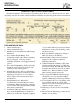
SECTION 1 – INTRODUCTION or go to their website at http://www.safercar.gov or write to: Administrator, NHTSA 1200 New Jersey Avenue S.E. Washington, D.C. 20590 You can also obtain other information about motor vehicle safety from the NHTSA website at http://www.safercar.gov OCCUPANT AND CARGO CARRYING CAPACITY LABEL This label is affixed in the driver’s area next to or near the Vehicle Certification Label.
SECTION 1 – INTRODUCTION VEHICLE CERTIFICATION LABEL This label is affixed to the lower driver side armrest panel, driver door, or the driver side door jamb, depending on model. It contains vehicle identification numbers and other important reference information. EXPLANATION OF DATA 1. Chassis manufacturer. 2. Chassis manufacture date. 3. Month and year of manufacture at Winnebago Industries®. 4.
SECTION 1 – INTRODUCTION SPECIFICATIONS AND CAPACITIES 25Q MercedesBenz® F50 Chassis 25R MercedesBenz® F50 Chassis 25T MercedesBenz® F50 Chassis Feature Number 1ME 1ME 1ME Length 25' 5" 25' 5" 25' 5" Winnebago Via 1 11' 11' 11' 7' 6.25" 7' 6.25" 7' 6.25" 39.0 cu. ft. 54.0 cu. ft. 92.0 cu. ft. Awning Length 16' 16' 16' Interior Height 6' 5" 6' 5" 6' 5" Interior Width 7' 3" 7' 3" 7' 3" 28 gal. 27 gal. 28 gal.
SECTION 1 – INTRODUCTION OWNER AND VEHICLE INFORMATION OWNER INFO Owner’s Name(s) __________________________________________________________________ Address __________________________________________________________________________ __________________________________________________________________________ VEHICLE INFORMATION Motorhome Model Number __________________________________________________________ Motorhome Serial Number ___________________________________________________________ Chassis Vehicle I
SECTION 2 – SAFETY AND PRECAUTIONS • • • • • • • • • Only seats equipped with seat belts are to be occupied while the vehicle is moving. Make sure all passengers have seat belts fastened. Lap belts should fit low on the hips and upper thighs. The shoulder belt should be positioned snug over the shoulder. For pregnant women: Never place the shoulder belt behind your back or under your arm. Adjust the lap belt across your hips/ pelvis, and below your belly.
SECTION 2 – SAFETY AND PRECAUTIONS WARNING Propane gas containers, gasoline, or other flammable liquids shall not be placed or stored onboard the vehicle because a fire or explosion may result. Propane gas containers are equipped with safety valves, which relieve excessive pressure by discharging gas to the atmosphere. Failure to comply could result in death or serious injury.
SECTION 2 – SAFETY AND PRECAUTIONS PROPANE GAS LEAK DETECTOR Your coach is equipped with a Propane Gas Leak Detector, similar to the one shown below. The leak detector sounds an alarm if an unsafe amount of propane gas is present inside the coach. battery during storage periods when the house battery will not be charged regularly by the engine or shoreline. Further Information See the manufacturer’s user guide provided in your InfoCase for further instructions.
SECTION 2 – SAFETY AND PRECAUTIONS CARBON MONOXIDE ALARM SMOKE ALARM Your coach is equipped with a Carbon Monoxide (CO) Alarm (located on the ceiling in the bedroom area.) The CO Alarm is powered by a 9-volt battery and has a sensor that is designed to detect toxic carbon monoxide gas fumes resulting from incomplete combustion of fuel. It will detect CO gas from any combustion source such as the furnace, gas range/oven, water heater, refrigerator, chassis engine, and electric generator engine.
SECTION 2 – SAFETY AND PRECAUTIONS FIRE EXTINGUISHER ELECTRICAL A dry chemical Fire Extinguisher is located near the main entrance door. • • Fire Extinguisher (Typical installation - your coach may vary according to model and floorplan) We recommend that you become thoroughly familiar with the operating instructions displayed on the side of the Fire Extinguisher and in the information supplied in your InfoCase.
SECTION 2 – SAFETY AND PRECAUTIONS MAINTENANCE • • • • Do not remove the radiator cap while engine and radiator are still hot. Always check coolant level visually at the see-through coolant reservoir. Never get beneath a vehicle that is held up by a jack only. Do not mix different construction types of tires on the vehicle, such as radial, bias, or belted tires, as vehicle handling may be affected. Replace tires with exact size, type, and load range.
SECTION 2 – SAFETY AND PRECAUTIONS Check inside and outside the vehicle to make sure that there are no people who could be harmed or obstacles that could cause damage due to room activation. Side Latch WARNING Bottom Latch Escape Window (View of interior left-hand side of window) -Typical View Side Latch Bottom Latch Escape Window (View of interior right-hand side of window) -Typical View SLIDEOUT ROOMS WARNING Your motorhome may have more than one slideout room.
SECTION 2 – SAFETY AND PRECAUTIONS MOLD, MOISTURE, AND YOUR MOTOR HOME Monitor your motorhome. Periodically check those hidden areas in corners, closets, and cabinets to assure mold is not present. What is Mold? What if I Find Mold? Molds are part of the natural environment. They are as old as the Earth itself and mold spores are almost everywhere at some level waiting to grow. Mold plays a part of nature by breaking down dead organic matter, such as fallen leaves and dead trees.
SECTION 2 – SAFETY AND PRECAUTIONS yourself, please exercise extreme caution and read all tire changing information in the chassis manual. Never get beneath a vehicle that is held up by a jack only. Some models, however, may have a swingdown spare tire carrier beneath the rear of the coach. Please follow all safety warnings and instructions for removing spare tire from the carrier. If You Get A Flat Tire Swing-Down Carrier (if equipped) • • DO NOT panic.
SECTION 2 – SAFETY AND PRECAUTIONS JUMP STARTING WARNING Stay out from beneath the motorhome while it is suspended by the towing assembly. Do not allow passengers to occupy a towed vehicle. Death or serious injury can result. WHEEL MOUNTING NUTS (LUG NUTS) The mounting bolts and nuts for the standard steel wheels are designed specifically for the type of wheel. See the following information and photos. Steel Wheels • The lug nut for steel wheels is a non-plated, hat-shaped, flange nut.
SECTION 3 – DRIVING YOUR MOTOR HOME The information in this section refers only to features installed or adapted to the dash and driver compartment area by Winnebago Industries®. It also includes passenger seating in the living area of the coach. Further Information See the chassis manual in your InfoCase for all original chassis related controls, instrumentation, switches, and other features.
SECTION 3 – DRIVING YOUR MOTOR HOME Rotating the Seat Toward Center of Coach If you wish to rotate the seats toward the center of the coach for additional lounge/dinette seating, follow Steps 1-3 as previously listed and: 5. Grasp front of seat and rotate around so the seat is facing the lounge area, as desired. position, lift UP on the Recline Lever and lean body forward. Allow the seat to return to the desired position and release the lever. Recline Lever Lowering the Seat 1.
SECTION 3 – DRIVING YOUR MOTOR HOME Lap Belts The lap belts must be worn as low as possible and fit snugly across the hip area. Always sit erect and well back into the seat. To gain full protection of the safety belt, never let more than one person use the same safety belt at any one time, and do not let the safety belts become damaged by pinching them in the doors or in the seat mechanism. After any serious accident, any seat belts which were in use at the time must be inspected and replaced if necessary.
SECTION 3 – DRIVING YOUR MOTOR HOME • • • Inspect the belts and hardware periodically. Check for cuts, frays, and loose parts. Damaged parts should be replaced. Do not remove or modify the belt system. Keep belts clean and dry. If the belts need cleaning, use only a mild soap and water solution. Do not use hot water. Do not use abrasive cleaners, bleach, or dyes. These products may weaken the belts. Replace any belt assembly that was used during a severe impact.
SECTION 3 – DRIVING YOUR MOTOR HOME Mirror Arm/Head Adjustment If you cannot adjust a mirror properly using the control switch, the mirror may need a coarse adjustment by rotating the mirror head. Power Sunvisor Switch (Located beneath dash radio) -Typical View HAZARD WARNING FLASHERS Mirror Head Pivot Lock • Loosen Allen head set screws to pivot mirror head. • Torque 75-100 in./lbs. NOTE: Set screws may be located on the opposite side of the mirror arm. Passenger side mirror is similar.
SECTION 3 – DRIVING YOUR MOTOR HOME 2. Remove two screws on the front of the air filter housing. Air Intake Hose Fastener Air Intake Hose/Fastener (View shown from beneath the front end of coach) Air Filter Housing (Located underneath the front hood) 3. Lift up air filter housing lid and replace filter. NOTE: To make removing the air filter easier, you may temporarily move the air intake hose by removing the fastener as shown in the following photo.
SECTION 3 – DRIVING YOUR MOTOR HOME Basic Operating Instructions Satellite Radio • –If Equipped Your coach may be equipped with a Sirius® satellite radio receiver that plays through your radio. See the receiver manufacturer’s information in your InfoCase for programming and operating instructions. • • • • • • • POWER ON/OFF - Push to turn ON or OFF. Push and Hold to turn screen OFF. Touch screen to turn back ON. MENU - Press to access USER SETTING MENU. Press and Hold to access SYSTEM SETUP MENU.
SECTION 3 – DRIVING YOUR MOTOR HOME by house batteries. If the House/Coach Battery Disconnect switch is OFF, the speakers will not emit sound. Radio/GPS/Rearview Monitor (Located on dash) Basic Operating Instructions Radio Power Switch (Located on lower dash area) • Press HOUSE to listen to the radio while parked without the ignition key on. • Press ENGINE (“ENG”) to listen while driving.
SECTION 3 – DRIVING YOUR MOTOR HOME temperature shown on the dash instrument panel may vary by up to three degrees. See the receiver manufacturer’s information in your InfoCase for programming and operating instructions. Rearview Monitor iPod Connection The rearview monitor feature of this system lets you see what is directly behind your coach for safety and maneuvering assistance. Sideview cameras also allow you to see what is beside you before turning or changing lanes.
SECTION 3 – DRIVING YOUR MOTOR HOME Radio Power Switch (Located on lower dash area) • Press HOUSE to listen to the radio while parked without the ignition key on. • Press ENGINE (“ENG”) to listen while driving. Battery Boost Switch (Located on lower dash area) • Press and Hold in the ON position while turning ignition key for emergency starting power. Further Information See the manufacturer’s user guide provided in your InfoCase for complete operating instructions.
SECTION 3 – DRIVING YOUR MOTOR HOME Diesel Exhaust Fluid Fill (Located under front hood) -Typical installation shown Further Information Refer to the chassis manual provided in your InfoCase for complete information and precautions. LIGHTS • To close, lift up fuel fill door into closed position and turn key clockwise. Be sure the door is fully locked before traveling. DIESEL EXHAUST FLUID FILL The Diesel Exhaust Fluid Fill is located under the front hood.
SECTION 3 – DRIVING YOUR MOTOR HOME VALVE STEM ACCESS (Mercedes-Benz® Sprinter Chassis) Front Wheel Valve Stem Access on 18-Hole Steel Wheel with Push-On Full Wheel Trim –If Equipped 1. Obtain a double angle push/pull truck tire gauge. 6. When tire pressure testing is complete, reinstall the valve stem cap (with the cap still retained in the hose extension end). 7. Remove hose extension from valve stem cap. 2. Locate the 6” hose extension (provided in your InfoCase).
SECTION 3 – DRIVING YOUR MOTOR HOME Rear Outer Dual Valve Stem Access NOTE: Rear Outer Dual is equipped with a fillthrough extension (no valve stem cap). 1. Obtain a double angle push/pull truck tire gauge. 4. Using the hose extension as a remote handle, unscrew the valve stem cap (retaining cap in the end of the hose extension).
SECTION 3 – DRIVING YOUR MOTOR HOME WARNING Make sure all replacement tires are of the same size and rating as those shown on your Vehicle Certification Label. SUSPENSION ALIGNMENT AND TIRE BALANCE The front suspension and steering system of this vehicle was factory aligned using highly accurate equipment prior to delivery to the dealership. However, alignment should be checked and adjusted after you have fully loaded the motorhome according to your personal needs.
SECTION 4 – APPLIANCES AND SYSTEMS The appliances installed in your motorhome are manufactured by reputable RV appliance makers and have been tested by independent laboratories to meet all applicable standards and codes set for RV appliances. See Section 2 - Safety and Precautions of this manual for any safety and precautions you need to take regarding the operation of your appliances.
SECTION 4 – APPLIANCES AND SYSTEMS • • To start up the refrigerator, press the Mode button for 2 seconds. The previously selected operating mode is displayed (e.g. 120, which means 120V). Press Mode again and you may change the operating mode to: AU (Automatic Energy Selection) or manually change to 120V, 12V, or Gas. NOTE: The 12V DC operation is only operational while the engine is running.
SECTION 4 – APPLIANCES AND SYSTEMS WARNING Portable fuel-burning equipment including wood and charcoal grills and stoves, shall not be used inside the recreational vehicle. The use of this equipment inside the recreational vehicle can cause fires or asphyxiation. Failure to comply could result in death or serious injury. To Light Range Top Burners • Push in desired control knob and turn to IGNITE position - and maintaining the knob pushed in, press down on the spark pump a few times to light burners.
SECTION 4 – APPLIANCES AND SYSTEMS Generator Start/Stop Switches and Hourmeter (Not available on coaches equipped with a diesel generator) See Section 6 - Electrical for generator startup/shut-down and generator hourmeter instructions.
SECTION 4 – APPLIANCES AND SYSTEMS • An interior light should be turned on to provide a small load which draws off the battery surface charge. Water Heater Switches Sensors See Water Heater information elsewhere in this section for operating instructions. Water Tank -Typical View Tank Capacities See “Tank Capacities” in Section 1 Introduction. Propane Gas Level Press the Tank Levels switch to show approximate propane tank level. The propane level is registered by a sending unit on the tank.
SECTION 4 – APPLIANCES AND SYSTEMS WATER HEATER - GAS/ ELECTRIC The Gas/Electric Water Heater has a dual power feature. It can operate from propane gas or 120-volt house current, or it can use both at the same time for quicker recovery at times when you are using a lot of hot water. See the Water Heater manufacturer’s operation manual provided in your InfoCase for complete operating instructions, safety warnings, and maintenance information before operating the Water Heater.
SECTION 4 – APPLIANCES AND SYSTEMS Water Heater Exterior Service Access Normally there is an air gap at the top of the water heater tank, which acts as a pressure buffer. In time, however, heated water may expand and fill this air gap, causing a slight increase in water pressure. This may cause the P-T valve to “weep” until the air gap is manually replaced. CAUTION Hot water can escape from tank causing injury. Operate this valve only when the water heater and engine cooling system are cold.
SECTION 4 – APPLIANCES AND SYSTEMS Further Information Refer to the manufacturer’s user guide provided in your InfoCase for further information, including operating precautions, and periodic maintenance. See “Coach Maintenance Chart” in Section 11 - Maintenance and Storage for recommended intervals. Thermostat Switch • Move to Heat or Gas position for furnace operation Temp Selector • Press up or down to select temperature -Typical View 2.
SECTION 4 – APPLIANCES AND SYSTEMS when outside temperatures begin to reduce the efficiency of the Heat Pump. The Heat Pump will not operate when the outside temperature falls below 36 degrees F. To Operate the Heat Pump Refer to the manufacturer’s user guide provided in your InfoCase for complete operating instructions.
SECTION 5 – PROPANE GAS PROPANE GAS SUPPLY The propane gas system supplies fuel for the gas range/oven, water heater, furnace, and refrigerator (while in gas mode). When used and handled properly, this system is safe and economical and provides modern living conveniences wherever you travel. See Section 2 - Safety and Precautions of this manual for other safety and precautions you need to be aware of related to propane.
SECTION 5 – PROPANE GAS DA NG E R Main Tank Valve Switch (Located near monitor panel area) -Typical View Main Tank Shutoff Switch (Located in driver side compartment) -Typical View NOTE: Both switches must be ON to allow propane supply to the coach. Propane gas flow can be stopped by turning either switch OFF. Turn switch OFF when propane gas supply is not needed to conserve house battery power.
SECTION 5 – PROPANE GAS phone directory yellow pages for locations of local propane gas refilling stations or bulk dealerships. NOTE: If you travel outside the U.S. with your motorhome, you may find butane or propane/butane mixtures available in addition to propane. Because gasburning RV appliances are designed to run on propane only, we recommend that you request straight propane only.
SECTION 5 – PROPANE GAS PROPANE GAS WARNINGS AND PRECAUTIONS WARNING It is illegal for vehicles equipped with propane tanks to travel on certain roadways or through certain tunnels in the U.S. To avoid inconvenience, check state regulations concerning flammable gas transportation. Propane cylinders shall not be placed or stored inside the vehicle. Propane cylinders are equipped with safety devices that relieve pressure by discharging propane to the atmosphere.
SECTION 5 – PROPANE GAS WARNING Visually inspect the pressure regulator vent periodically for blockage by accumulated debris or insect nests, etc. Vent obstruction could result in excessive pressure causing fire or explosion, which could result in death or serious injury. If an obstruction exists, have the regulator serviced by a qualified service center. -Typical installation shown Regulator Freeze-up Regulator freeze-ups are caused by the presence of moisture in fuel.
SECTION 5 – PROPANE GAS This means that in extremely cold weather when a large volume of gas is being used by the furnace for heating, it is possible to experience a loss of gas pressure. At first, this problem may appear to be caused by an empty tank or a regulator freeze-up, but is actually caused by failure of the liquid gas to vaporize as fast as it is needed by the furnace. The demand for propane to produce heat increases to the point where the gas cannot vaporize fast enough to keep the furnace going.
SECTION 6 – ELECTRICAL ELECTRICAL CAUTIONS • • • • • • Careless handling of electrical components can be fatal. Never touch or use electrical components or appliances while feet are bare, while hands are wet, or while standing in water or on wet ground. Improper grounding of the vehicle can cause personal injury. Do not plug the utility power cord into an outlet which is not grounded and do not adapt the plug to connect to a receptacle for which it is not designed.
SECTION 6 – ELECTRICAL 30 Amp Receptacle The power cord is designed to ground the electrical system through the receptacle. It is also designed to carry the amperage output of most campground outlets. If the electrical receptacle to be used is designed to mate with the prongs of the power cord plug, the electrical connection can be expected to carry rated load.
SECTION 6 – ELECTRICAL NOTE: The inverter is not intended for steady use while “dry camping”. Batteries will deplete quickly with use of the inverter. The inverter is intended for limited, short term power usage when not connected to shoreline or generator power. The inverter can also be used while driving the motorhome because the engine alternator will charge the batteries while driving.
SECTION 6 – ELECTRICAL 120-Volt Circuit Breakers 12-Volt House Fuses Inverter Control Panel (Located near monitor panel) -Typical View When the inverter is not being used, it should be shut off at the control panel. The inverter could drain the house batteries if the shoreline is not connected to external power and the House/ Coach Battery Disconnect switch is on. Further Information See the inverter control panel instructions in your InfoCase for complete instructions and charging setup directions.
SECTION 6 – ELECTRICAL condition of the battery. If it is below “full charge”, the Charging Section will start charging the batteries. If the house batteries have been extremely discharged, they will accept charge at a relatively high amperage rate. If they are only slightly discharged, they will charge at a lower amperage rate. The rate of charge will decrease as the batteries reach “full charge”, then will continue “trickle” charging at a very low amperage rate.
SECTION 6 – ELECTRICAL If the GFCI keeps tripping, have the electrical system checked and repaired, if necessary, before using again. To use the 120-volt Generator, plug the power cord into the Generator receptacle within the utility compartment before starting the Generator. • Push to Reset circuit after monthly testing or ground fault tripping. • Push to Test at least monthly. Should break circuit. Press Reset button to reconnect.
SECTION 6 – ELECTRICAL To Stop the Generator • Press the Display ON/Gen OFF button. LP Generator Start/Stop Buttons (Located on monitor panel) -Typical View Press to Stop/Prime Diesel Generator Start/Stop Buttons (Located near monitor panel) -Typical View Generator Hourmeter The Generator hourmeter registers the total number of hours that the Generator has been operated. Press the GenSet Meter button once to get reading.
SECTION 6 – ELECTRICAL • Park the vehicle so that the wind will carry the exhaust away from the vehicle. Also, note the position of other vehicles to be sure their exhaust will not enter your vehicle. • Do not operate the Generator engine while parked if vegetation, snow, buildings, vehicles, or any other object can deflect the exhaust under or into the vehicle. Check Generator oil level frequently during periods of use.
SECTION 6 – ELECTRICAL House Batteries House/Coach Battery Disconnect Switch (Located near entrance door or end of galley, depending on model) -Typical View Chassis Battery The chassis (starting) battery is located in a compartment “well” in the floor beneath carpet ahead of the driver seat. BATTERY ACCESS House Batteries The house batteries are located in a compartment beneath the interior entrance steps. Unfasten the step retainer, then lift the step upward and remove to service batteries.
SECTION 6 – ELECTRICAL The two best defenses against sulfating and insufficient charge are to: Chassis Battery Connector (Located to the right of the accelerator pedal) Further Information See the chassis manual provided in your InfoCase for details on access and servicing. NOTICE Always refasten battery retainers when returning a battery to the compartment. BATTERY CARE Lead-acid type batteries are electro-chemical devices for storing and releasing electrical charge.
SECTION 6 – ELECTRICAL WARNING Before removing any battery cables or battery, make sure all 12-volt equipment in the motorhome is off and the power cord has been disconnected. Be sure to replace the battery terminal boot, if supplied, back onto the positive terminal after servicing. Care must be taken to avoid pinching the cable between any metal parts. Should the cable be damaged, a short circuit could result in personal injury or damage to equipment. Replace any damaged cables at once.
SECTION 6 – ELECTRICAL House 12-Volt Fuses (Located on right-hand side of Power Converter) -Typical View Automotive Chassis and House 12-Volt Circuit Breakers (Located in passenger side compartment) * Turn latches to remove cover The fuse panel accepts only blade type plug-in fuses. Always replace fuses with those of the same amperage rating. 30 30 Functional Non-Functional Battery Charge Meter See related item under “Systems Monitor Panel” in Section 4 - Appliances and Systems.
SECTION 7 – PLUMBING FRESH WATER SYSTEM Water Pressure Regulators Because city water pressure varies from location to location, we recommend obtaining an in-line water pressure regulator to prevent damage to any components, connections, and seals in your fresh water system. These devices simply connect in-line between the supply hose and the city water input on the coach. We recommend regulators that control water pressure to 50 psi. max.
SECTION 7 – PLUMBING Fresh Water Valve (Located in water service center) 4. Turn city water supply ON. 5. Use the level display on the monitor panel to oversee filling of the tank, or when the tank is full, water will flow from tank vent tube beneath coach and out of the Gravity Fill door. NOTICE Do not leave fresh water connection unattended when filling tank. Failure to comply may result in tank expansion and property damage. 6.
SECTION 7 – PLUMBING NOTE: Ensure the Fresh Water valve is in NORMAL position to use the water pump. If the valve is in Tank Fill position, the pump will run continuously without delivering water. Method 2 - Filling the Fresh Water Tank Through Gravity Fill -If Equipped Always fill the fresh water tank at an approved potable water filling facility or a known purified drinking water source.
SECTION 7 – PLUMBING • • Remove the bowl and pull the strainer screen out of the bowl to tap out any particles and rinse clean. Insert the strainer screen back into the bowl, then screw the bowl back onto the strainer assembly. NOTE: You must also empty the strainer when winterizing your coach to avoid water freezing and cracking the filter bowl.
SECTION 7 – PLUMBING • Before using the water for drinking, run a few gallons of water through the filter and discard water to avoid consuming carbon dust or particles that may have been present in the new filter cartridge. Diverter Plug • Install the diverter plug into the filter socket for winterization or if water must be used while the filter is removed from the socket. The diverter plug is installed in the same manner as the water filter.
SECTION 7 – PLUMBING DISINFECTING YOUR FRESH WATER SYSTEM (As required by NFPA®1192 Standard on Recreational Vehicles) To ensure complete disinfection of the potable water system, it is recommended that the following procedure be followed on a new system, one that has not been used for a period of time, or one that could have become contaminated. This procedure is also recommended before long periods of storage, such as over winter. Disinfecting with Gravity Fill 1.
SECTION 7 – PLUMBING If items are placed into the shower tub before shower valve vacuum release is complete, they may become wet. EXTERIOR SHOWER/WASH STATION –If Equipped The Exterior Shower/Wash Station feature allows you to do things such as rinse off sand or salt after a swim, rinse off muddy boots, or bathe your pet outside the coach. Some models may have a Water Pump switch located near the shower faucet for convenience.
SECTION 7 – PLUMBING tank contains the waste water from the galley sink and shower, and may include bathroom lavatory. See “Specifications” in Section 1– Introduction for tank capacities for your model. 1st - Pull Black Waste Tank Drain valve to drain Black Water (sewage) tank – then close. Dumping Holding Tanks 1. Remove sewage drain hose from cylindrical compartment near water service center or LP fill, depending on model. 2. Remove dust cap from sewage drain outlet and connect sewage drain hose.
SECTION 7 – PLUMBING Using On-Site Sewer Hook-Ups Waste Pump The sewage drain hose may remain attached to the sewage drain outlet while the motorhome is parked and connected to an on-site sewage hookup. When using a sewer hook-up, keep the dump valves closed until a tank becomes full or when preparing to leave the site. This keeps the solids in suspension, allowing them to be carried out with the liquids when the dump valve is opened.
SECTION 7 – PLUMBING Dumping Holding Tanks 1. Remove sewage drain hose from passenger rear compartment or cylindrical compartment near water service center, depending on model. 2. Remove dust cap from sewage drain outlet and connect sewage drain hose. Be sure it is firmly attached. NOTE: DO NOT OPEN BOTH VALVES AT ONCE. Do not open the Gray Waste Tank Drain valve until the black tank is drained and dump valve closed to avoid sewage back-up into gray tank.
SECTION 7 – PLUMBING 6. Add an odor control chemical to the sewage holding tank through the toilet. These chemicals are available at most RV stores. 7. Rinse sewage drain hose thoroughly with water and stow. • Model 25R - Located above thermostat near rear TV. The illuminated switch will glow when the power is on. NOTE: We recommend that you dump all holding tanks before traveling to avoid carrying unnecessary weight.
SECTION 7 – PLUMBING DRAIN Refer to the “Water System Drain Valve Locations” chart at the end of this section for locations on your model. DRAIN CLOSE CLOSE LINE-END VALVE IN-LINE VALVE Waterline Drain Valves (Typical) Normal Flow By-Pass Mode CAUTION Waterline Drain Valves -Typical installation shown Leave bypass valve handle in NORMAL FLOW position if draining water and blowing out waterlines. Place in BYPASS position ONLY when using antifreeze solution in waterlines.
SECTION 7 – PLUMBING left in the shower line. Also place the tip of your finger into the city water inlet and gently press the backflow valve “button” in the center of the inlet to drain any water trapped in the inlet line. Using exterior shower to drain waterline (Typical view - appearance on your coach may differ) 4. Remove the Cold Water Filter Cartridge (if equipped). Remove the filter cartridge from the filter assembly below the galley sink.
SECTION 7 – PLUMBING 11. Turn air pressure off. Disconnect water purge adapters. Recap the city water inlet to avoid contamination by dirt or insects. Pressure-Temperature Relief Valve (Lift handle only when water heater is cold) 8. Connect Air Pressure. After water has stopped draining at all faucets and drain valves, leave faucets open and connect a “blow-out” plug to the city water connection on the coach. Then use a compressed air hose regulated to 30 psi or less to force air through the system.
SECTION 7 – PLUMBING Method 2 – Antifreeze Fill Procedure (Fill plumbing lines with RV water system antifreeze) NOTE: As an alternative to totally draining the waterlines, you may winterize tanks and lines by filling them with non-toxic RV water system antifreeze through the plumbing system. This product is available from your dealer and from most RV supply stores and national retail outlets. Follow directions on the container to determine the correct amount to use for your coach.
SECTION 7 – PLUMBING . 4. Turn the Winterization valve handle so it points toward the antifreeze siphon tube. This will allow the siphon tube to draw non-toxic RV antifreeze into the waterlines. (See “Water System Drain Valve Locations” chart at the end of this section for location on your model).
SECTION 7 – PLUMBING When Done Adding RV Antifreeze 8. Turn the Water Pump switch OFF. 9. Turn the Winterization valve so it points toward the waterline connected to the water pump. This will stop the flow from the antifreeze siphon tube and revert the tank line flow to the water pump. 10. Replace the protective cap onto the end of the antifreeze siphon tube to keep out insects or debris when not in use. Drain Water Heater 11.
SECTION 7 – PLUMBING Waste Pump Drain (Located underneath rear driver side of coach) * Models 25T and 25Q only • • Pour 2 gallons of RV antifreeze down the shower OR galley sink drain. Press and hold the Waste Pump switch for approximately 5-10 seconds to get antifreeze into the pump.
SECTION 7 – PLUMBING WATER SYSTEM DRAIN VALVE LOCATIONS Model 25T System Drain Valve Locations Waterlines • Two (2) drain valves in the water service center and two (2) drain valves located through an access hole beneath the bed. Also, place the tip of your finger inside the city water connection and gently press the backflow valve (small “button” in center of connector) to drain any water left in the city waterline. Water Tank • One (1) valve located in the water service center.
SECTION 7 – PLUMBING 25R 25Q Waterlines • Two (2) drain valves in the water service center and also beneath the wardrobe (behind flip-down door). Also, place the tip of your finger inside the city water connection and gently press the backflow valve (small “button” in center of connector) to drain any water left in the city waterline. Water Tank • One (1) valve located in the water service center. Water Heater • Drain plug on outside of coach behind service door. Use socket to remove drain plug.
SECTION 8 – ENTERTAINMENT TV – 12V LED -If Equipped The LED flat panel TV is powered by 12-volt DC current. The 12-volt current is supplied from the house batteries, or from the power converter when connected to shoreline power or running the generator. To Extend TV • Open the wooden cabinet cover located on the inboard side of TV. • Extend TV. NOTE: The 12-Volt TV Master Power switch must be ON to operate the TV.
SECTION 8 – ENTERTAINMENT Supplement. See your InfoCase for specific operating guides for audio and video components. DVD PLAYER WITH DELUXE SOUND –If Equipped The DVD player is a selectable function of the multi-featured audio system. The player unit contains DVD/CD/MP3/AM-FM stereo radio. It also accepts portable audio player inputs and it also functions as an alarm clock.
SECTION 8 – ENTERTAINMENT Further Information See the manufacturer’s quick reference guide provided in your InfoCase for complete feature descriptions and operating instructions. TV ANTENNA - DIGITAL (Jack® Digital HDTV Over-the-Air Antenna) Your coach is featured with a digital antenna, which provides crystal clear digital HD reception of over-the-air channels in addition to superior broad reception range. The digital antenna is equipped with a built-in amplifier for maximum VHF and UHF programming.
SECTION 8 – ENTERTAINMENT Power Switch We recommend that you read the satellite dish manual thoroughly to understand the system completely before attempting any setups or adjustments. • The coach must be level before attempting to adjust the antenna dish. • There must be a clear “line of sight” to the satellite. Mountains, buildings, trees, telephone poles and other obstructions can all block the satellite signal from reaching the dish.
SECTION 8 – ENTERTAINMENT TV DIGITAL SATELLITE SYSTEM WIRING Your coach is pre-wired for installation of a digital satellite TV system. Coaxial cable and high definition component cable connections are available to hook up your satellite receiver and are located near the entertainment center cabinet. A second connection may be included inside a cabinet in the bedroom for the rear TV (if equipped).
SECTION 9 – FURNITURE AND SOFTGOODS SLEEPING FACILITIES Disengaged WARNING Sleeping facilities are not intended for use while vehicle is in motion. For safety, passengers must use safety belted seating positions while vehicle is in motion. FRONT BUNK Engaged Bunk Storage Latches (Located on each side of bunk) To lower bunk for use 1. Move both the driver and passenger cab seats forward and recline completely to allow clearance for the bunk to be lowered.
SECTION 9 – FURNITURE AND SOFTGOODS 2. Lay fitted cushion over the extended bed board. WARNING Engage bunk storage latches. Failure to do so can allow bunk to drop, which may result in injury or loss of vehicle control. See Operator’s Manual. FLEX BED (Model 25T) Your coach is featured with a Flex Bed system, which sleeps as two twin beds - or you can choose to easily convert them into a queen size bed. 3. Reverse steps to store bed back into twin bed position. 1.
SECTION 9 – FURNITURE AND SOFTGOODS 2. Arrange the cushions to fill in the open spaces. 2. Remove rectangular seat back cushion and set aside. To convert bed back into stored position, remove cushions and push bed board against wall. NOTE: Ensure the bed is in the stored position (flush against driver side wall with cushions removed) before retracting the slideout room to prevent possible property damage. 3.
SECTION 9 – FURNITURE AND SOFTGOODS 6. Turn the Inflate/Deflate switch “clockwise” to the INFLATE position. NOTE: Pump will automatically turn off once selected firmness level is reached and the Inflate/Deflate switch will automatically return to the OFF position. 4. Unfold the air mattress so it is covering the sofa bed. NOTE: The air mattress is plugged into an AC power outlet behind the sofa. It may be necessary to press the “Reset” button on the galley GFCI outlet before operating. 5.
SECTION 9 – FURNITURE AND SOFTGOODS 2. Turn the Inflate/Deflate switch “counterclockwise” to the DEFLATE position for complete air removal. NOTE: Pump will automatically turn off and the Inflate/Deflate switch will automatically return to the OFF position upon complete deflation. 6. Reinstall two front seat back cushions. Further Information See the air bed manufacturer’s user guide provided in your InfoCase for complete operating instructions, safety precautions, and repair information.
SECTION 9 – FURNITURE AND SOFTGOODS 3. Arrange dinette cushions to cover bed area. DINETTE CONVERSION –If Equipped (Typical view – your coach may differ) Dinette Table Setup 1. Remove dinette table and pedestal leg from underneath the sofa. 2. Insert dinette pedestal leg into the metal receiver on the floor. Your coach may be equipped with two metal receiver locations: • One located in front the sofa. • The other located behind the driver and passenger cab seats. Bed to Dinette 1.
SECTION 9 – FURNITURE AND SOFTGOODS 3. Place dinette table securely onto the dinette pedestal leg. • • To raise the translucent screen, pull bottom latch outward and let the screen retract. For daytime room darkening or nighttime privacy, pull entire shade upward to desired position. WINDOW SHADES/SCREENS Your coach is featured with multi-positioning window shades and screens that can be used for light filtering, outside airflow, bug protection, daytime room darkening, or nighttime privacy.
SECTION 9 – FURNITURE AND SOFTGOODS ROLLER SHADES (MANUAL) SOLAR DAY/NIGHT –If Equipped Your coach may feature two-stage day/night roller shades that provide both solar heat protection and light-blocking capabilities. The shade can easily be lowered by hand to any position, then retracted with a slight downward pull movement. When raising the shade, there is no need to hold onto the bottom of the shade - just simply let it go and it will rise at a slow, controlled rate.
SECTION 9 – FURNITURE AND SOFTGOODS Therefore, since wood is a product of nature and will have certain natural characteristics and variances, they are not covered under the warranty.
SECTION 10 – SLIDEOUT ROOMS SLIDEOUT ROOM TRAVEL LOCK • Place T-shaped • Rotate cylinder rod end against body to loosen back side of or tighten ends slideout frame NOTICE Release and remove Slideout Prop-Lock Rod before attempting to extend slideout room. Damage to the vehicle will result if this is not done. Position and secure Prop-Lock before driving vehicle. See following instructions. Slideout Room Prop-Lock Rod Typical view of forward end of retracted slideout room directly behind driver seat.
SECTION 10 – SLIDEOUT ROOMS SLIDEOUT ROOM OPERATION – ELECTRIC WARNING Slideout Room Keylock The key to turn the master keylock “off” is attached to the lock rod. This is to remind you that the rod is removed prior to turning the switch. Your motorhome may have more than one slideout room. Understand which switch operates which slideout room prior to operation. Make sure all slideout rooms are clear of people who could be harmed or obstacles that could cause damage prior to operating any slideout rooms.
SECTION 10 – SLIDEOUT ROOMS The slideout room system uses 12-volt DC motorized mechanisms with an electronic control system to provide smooth operation and positive weather seal. NOTE: We recommend that you KEEP THE ENGINE RUNNING WHILE EXTENDING OR RETRACTING SLIDEOUT ROOMS so the engine alternator can provide maximum power for proper operation of the slideout mechanisms. WARNING CRUSH HAZARD. Keep people and objects clear of the inside and outside of the slideout room when operating.
SECTION 10 – SLIDEOUT ROOMS compartments, which could be crushed or cause damage to floor covering or cabinets when the room is retracted. NOTICE Because the slideout roof is drawn into the interior of the coach when retracted, be sure there is no debris, such as excessive dirt, tree seeds, twigs, leaves, etc. on the roof before retracting. Retract Procedure: See “Before Retracting!” before proceeding.
SECTION 10 – SLIDEOUT ROOMS • The circuit breaker may be tripped. The circuit breaker labeled “Slideout Power” is located on a panel on an interior wall of the passenger side compartment just behind or ahead of the entrance door or on the side of the passenger seat base, depending on model. Problems Retracting the Room • Set the Park Brake if the Engage Park Brake light flashes while pressing the Retract (IN) button.
SECTION 10 – SLIDEOUT ROOMS In the event of a total system failure where Manual Mode cannot be used, the crank-in method may be used to retract or extend the room. See Slideout Emergency Retraction elsewhere in this section. Further Information Problems Extending the Room SLIDEOUT EMERGENCY RETRACTION (POWER GEAR®) • Set the Park Brake if the Engage Park Brake light flashes while pressing the Extend (OUT) button.
SECTION 10 – SLIDEOUT ROOMS 1) Lift tab inside protrusion on boot to disengage motor brake 2) Disconnect motor power lead from wiring harness Accessing the Motor/Gear Assembly Model 25T • Remove oval access panel inside front driver side compartment. 3) Use 3/4” socket on gearbox shaft to crank room in Motor/Gear Assembly Access Panel (Located inside driver side front compartment) * Model 25T shown Slideout Motor/Gear Assembly -Typical installation shown 4.
SECTION 10 – SLIDEOUT ROOMS Rear Motor/Gear Assembly (Located beneath bed - remove mattress and removable panel to access) * Model 25Q shown GENERAL SLIDEOUT CARE • • • • Keep slideout room seals clean. Clean the floors inside the coach before retracting the slideout room to avoid floor scratches or carpet pile snags. Wipe outer slideout room seals occasionally with talc or 303 brand protectant for smooth, quiet operation.
SECTION 11 – MAINTENANCE AND STORAGE SEALANTS – INSPECTION AND GENERAL INFORMATION NOTE: Proper sealant inspection includes not just visual observation but running a finger along sealant seams to verify proper adhesion to the surface. Any loosened areas must be replaced. • Have the sealant replaced if you notice any of the above. Your local Winnebago Industries dealer has the correct and necessary parts and experience to help you maintain your sealants.
SECTION 11 – MAINTENANCE AND STORAGE weight to the vehicle. This, in effect, reduces the amount of cargo you can carry and remain within GVWR and GAWR limits. Corrosive materials, such as those used for ice and snow removal and dust control, can also accumulate on the underside of a vehicle. These materials should be removed by flushing the undercarriage regularly with water, especially horizontal surfaces, cavities, and other areas where mud and other deposits may collect.
SECTION 11 – MAINTENANCE AND STORAGE Washing • • • • Commercial vehicle wash facilities should be strictly avoided! They will scratch your RV! Truck-style wash centers have highpressure wands that emit higher than necessary water pressures and the brushes are very aggressive. Most truck wash brushes are made from a heavy plastic for durability and are under heavy pressure. They are designed to clean heavy road films on semi trailers and are often dirty.
SECTION 11 – MAINTENANCE AND STORAGE • • Avoid paste waxes. They sometimes have fillers and additives that give a very short term result. Stay away from silicones in polishes and soaps. Buffing compounds remove some of the mil film of the clearcoat, so we recommend that only professionals or very experienced users apply this type of product. Inspection A motorhome exterior is subjected to many physical forces and environmental conditions.
SECTION 11 – MAINTENANCE AND STORAGE NOTICE Do not use citrus-based cleaners on polycarbonate finishes. Citric compounds will damage the high-gloss surface, causing it to appear dull or “flat”. Always test a cleaning product on a hidden area to be sure it will not cause damage to the appearance of the part. Here is a list of mild cleaners that may be used safely: • Car washing soap and water • Glass cleaners without ammonia • Mineral oil • Multipurpose cleaners (such as Fantastik®, Formula 409®, etc.
SECTION 11 – MAINTENANCE AND STORAGE shades should be closed when the motorhome is parked for an extended period of time. • For stubborn stains, use cleaner-degreaser. UltraLeather Cleaning Chart Type of Stain WARNING When cleaning upholstery and fabric, do not use lacquer thinner, nail polish remover, laundry soaps, or bleach. Never use carbon tetrachloride, gasoline, or naphthalene for any cleaning purpose.
SECTION 11 – MAINTENANCE AND STORAGE CABINETRY – CLEANING Wooden items may be cleaned with a soft cloth and a good quality wood finish cleaning product. Vinyl simulated wood panels may be cleaned with a mild, water-based cleaner and a soft cloth. Do not use solvents on vinyl wood panels. NOTE: Many cabinetry and furniture items throughout this motorhome are constructed either partially or completely of real hardwoods.
SECTION 11 – MAINTENANCE AND STORAGE • • • Do not use abrasive powder detergents that could ruin the surface finish. Do not use wool, abrasive brushes, or tools that have previously cleaned other metals, because as well as scratching the surface, they can generate contamination and unattractive stains. Do not use silver cleaners. GALLEY SINK Stainless Steel Care and Cleaning Instructions The stainless steel sink can usually be cleaned with water and soap or detergent using a soft cloth or sponge.
SECTION 11 – MAINTENANCE AND STORAGE • Protect flooring from prolonged direct sunlight exposure. BATHROOM Treatment of Stains Toilet Acids, alkali, alcoholic beverages, coffee, soft drinks, ketchup, fruit, fruit juices, food, vegetables, mustard, ink, and iodine: For instructions on the care of your toilet, refer to the information in your InfoCase. • Remove the stain with lukewarm water and a cloth or sponge.
SECTION 11 – MAINTENANCE AND STORAGE 4. Clean and defrost the refrigerator. Prop the door open slightly to allow any odors to dissipate. Place an open box of baking soda inside the refrigerator to help absorb odors. 5. Fully charge the batteries. Batteries must have at least 80% charge to survive freezing temperatures and long period of non-use.
SECTION 11 – MAINTENANCE AND STORAGE 13. Start refrigerator and check for proper cooling. 14. Clean wall and counter surfaces. 15. Replace batteries, if necessary, and check out electrical system to make sure all lights and electrical components operate. 16. Check tires for proper cold inflation pressure. See “Vehicle Certification Label” in Section 1 - Introduction. 17.
SECTION 11 – MAINTENANCE AND STORAGE COACH MAINTENANCE CHART These recommendations apply for normal recreational use. Heavy duty or full-time use may require more frequent maintenance intervals.
SECTION 11 – MAINTENANCE AND STORAGE COACH MAINTENANCE CHART These recommendations apply for normal recreational use. Heavy duty or full-time use may require more frequent maintenance intervals. As Necessary Every Year Every 6 Months Every 3 Months Monthly Weekly Before Each Use Always use specified sections or manufacturer’s guide for further information and instructions.
SECTION 11 – MAINTENANCE AND STORAGE COACH MAINTENANCE CHART These recommendations apply for normal recreational use. Heavy duty or full-time use may require more frequent maintenance intervals. As Necessary Every Year Every 6 Months Every 3 Months Monthly Weekly Before Each Use Always use specified sections or manufacturer’s guide for further information and instructions.
SECTION 12 – MISCELLANEOUS NOTE: Your motorhome’s load capacity is designated by weight, not by volume, so you cannot necessarily use all available space when loading your motorhome. • Store or secure all loose items inside the motorhome before traveling. Possible overlooked items such as canned goods or small appliances on the countertop, cooking pans on the range, or free-standing furniture items can become dangerous projectiles during a sudden stop or evasive maneuver.
SECTION 12 – MISCELLANEOUS You will first drive only your front wheels onto the scale pad, then drive ahead so that the whole vehicle is on the scale, then finally pull off until just the rear wheels are on the pad. Front GAWR (Front Axle Only) GVWR - Whole Vehicle (All Axles) Rear GAWR (Rear Axle Only) You will receive a weight “ticket” that states your current Front Gross Axle Weight, Rear Gross Axle Weight, and Gross Vehicle Weight.
SECTION 12 – MISCELLANEOUS axle is 12,000 lbs., then the load on each rear dual set (left rear duals or right rear duals) should not exceed 6,000 lbs. Tires must be filled to the recommended air pressure for the highest loaded tire set on that axle. For example, on the rear axle, if the left side weighs more than the right, fill the left tires to the pressure required for that weight, then fill the right tires to the same pressure as the left ones.
SECTION 12 – MISCELLANEOUS Before descending a steep or long grade when towing a trailer, reduce speed and shift into a lower gear to control vehicle speed. Avoid prolonged or frequent application of brakes which could cause overheating and brake failure. TRAILER WIRING CONNECTOR Your coach is pre-wired for trailer or car towing lights with a 7-pin socket. The following diagram shows proper connection of trailer or tow vehicle wiring to the coach light system.
SECTION 12 – MISCELLANEOUS this definition, the “trailer” can be a trailer, a vehicle towed on a dolly, or a vehicle towed by means of a tow bar. GCWR is typically specified based on durability and performance of the tow vehicle drive train: engine and cooling systems, transmission, drive line, drive axle, and others. The tow vehicle brakes may be rated for operation at GVWR, not GCWR.
SECTION 12 – MISCELLANEOUS Automatic Mode - Entry Step Switch ON (Step Operates with Door) With the Step switch in the ON position, the step is in Automatic Mode. This means it will extend and retract automatically whenever the screen door is opened or closed. This feature is intended to prevent injury or damage by an extended step while the vehicle is moving. Further Information For additional information on the step, see the manufacturer’s operators manual included in your InfoCase.
SECTION 12 – MISCELLANEOUS If the window will not open after three or more full turns of the knob, the glass may be stuck to the sealing gasket. Go to the outside of the coach and gently free the glass with your fingers. A periodic light dusting of talcum powder on the gasket should prevent this from recurring. Horizontal Slider Windows Swing the latch handle straight out or up (depending on the style of window). Grasp the sliding window edge frame and slide the window to the side.
SECTION 12 – MISCELLANEOUS Closing the Windows To close window, extend all the way out (past the third notch setting) and the window will retract. Grab one of the window latches and pull window toward you and secure all four latches into locked position. POWER ROOF VENTILATOR Lounge, Galley, or Bath Area –If Equipped The vent dome is raised and lowered using the Dome Crank knob on the fan. The turbine fan will start automatically as the vent is raised, and stop as the vent is lowered.
SECTION 12 – MISCELLANEOUS Press to Retract Press to Extend Power Awning Switch (Located near entrance door) -Typical View Operating the Awning • Press and Hold the Power Awning switch until the awning is in the desired position, then release. Ignition Lockout System The Ignition Lockout System will disable the extend function while the vehicle ignition key is in the On position. With this feature, the Awning will only extend when the vehicle ignition key is in the Off position.
About this Manual ....................................... 1-1 Air Conditioner Filter .................................. 4-9 Air Conditioner/Heater – Automotive (Dash) ........................................................ 3-5 Audio-Video System Basic Operation ......... 8-1 Bathroom ................................................... 11-9 Battery Access ............................................. 6-9 Battery Boost Switch ................................. 3-10 Battery Care ...............................
Index Owner and Vehicle Information .................. 1-6 Plastic Parts – Cleaning ............................. 11-4 Power Awning ........................................... 12-8 Power Center ................................................ 6-4 Power Roof Ventilator ............................... 12-8 Power Sunvisor ............................................ 3-5 Pre-Delivery Inspection ............................... 1-2 Pressure-Temperature Relief Valve ............. 4-6 Propane Gas Furnace ..........