spot welder 230 volt Model 45690 assembly and Operating Instructions Visit our website at: http://www.harborfreight.com Read this material before using this product. Failure to do so can result in serious injury. Save this manual. Copyright© 2001 by Harbor Freight Tools®. All rights reserved. No portion of this manual or any artwork contained herein may be reproduced in any shape or form without the express written consent of Harbor Freight Tools.
SPECIFICATIONS TABLE ITEM DESCRIPTION Electrical Input Requirements 230 Volt Rated Output 1.5 KVA @ 50% Duty Cycle Output Amps 5,500 +/- 10% Material Capacity 1/8” Thick, Mild Steet Tong Length 6” Overall Dimensions 13” x 6” x 4.5” Net Weight 23.5 Lbs. SAVE THIS MANUAL You will need this manual for the safety warnings and precautions, assembly, operating, inspection, maintenance, and cleaning procedures, parts list and assembly diagram. Keep your invoice with this manual.
8. DO NOT OVERREACH. Keep proper footing and balance at all times to prevent tripping, falling, back injury, etcetera. 9. STAY ALERT. Watch what you are doing at all times. Use common sense. Do not use this product when you are tired or distracted from the job at hand. 10. CHECK FOR DAMAGED PARTS. Before using this product, carefully check that it will operate properly and perform its intended function. Check for damaged parts and any other conditions that may affect the operation of this product.
5. DO NOT FORCE THE EQUIPMENT. This Spot Welder will do the work better and safer at the speed and capacity for which it was designed. 6. AVOID UNINTENTIONAL STARTING. Make sure you are prepared to begin work before turning the Control Switch (part #25) “ON”. 7. Caution: Never touch the Upper and Lower Tongs (parts #46, #47) when welding a workpiece. Allow the Tong Tips (part #48) and the workpiece to cool before handling. (See Figures A, B, E, and Assy. Diagram.) 8.
UNPACKING When unpacking, check to make sure all parts shown on the Parts List (page 12) are included. If any parts are missing or broken, please call Harbor Freight Tools at the number shown on the cover of this manual as soon as possible. ASSEMBLY INSTRUCTIONS NOTE: For additional references to the parts listed below, refer to the Assembly Diagram on page 13 of this manual. To Attach The Upper And Lower Tongs: 1.
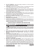
10. Re-tighten the four Cap Screws (parts #3, #11). OPERATING LEVER (#5) CAP SCREW (#3) TOP TONG HOLDER (#12) BOTTOM TONG CLAMP (#35) UPPER TONG (#46) HEX JAM NUT (#10) HEX JAM NUT (#10) TONGTIP (#48) HEX NUT (#20) TOP TONG TONG CLAMP (#13) INSULATOR (#33) LOWER TONG (#47) CAP SCREW (#34) FIGURE A TONG ALIGNMENT UPPER TONG (#46) TONG TIPS (#48) UPPER TONG (#46) TONG TIPS (#48) LOWER TONG (#47) LOWER TONG (#47) FIGURE B To Attach The Handle To The Spot Welder: 1.
2. Next, Attach the complete Handle Assembly (parts #17, #18, #19, #20) to the Front Housing (part #28) of the Spot Welder, using the four Hex Head Screws (part #16). (See Figure D, and Assy. Diagram.) WASHER HEX NUT (#20) HANDLE (#17) BOLT (#19) HANDLE BRACKET (#18) FIGURE C POWER SWITCH (#25) (#25) HEX SCREW (#16) FIGURE D To Attach Tong Tips To The Spot Welder: 1. Caution: Prior to attaching the Tong Tips (parts #48), make sure the Spot Welder is disconnected from its electrical power source.
OPERATING INSTRUCTIONS NOTE: For additional references to the parts listed below, refer to the Assembly Diagram on page 13 of this manual. To Adjust The Tong And Operating Lever Pressure: 1. Caution: Prior to adjusting the Tongs (parts #46, #47) and Operating Lever (part #5) pressure, make sure the Spot Welder is disconnected from its electrical supply source. 2. NOTE: Excessive Tong (parts #46, #47) can damage the Tong Tips (part #48).
REAR HEX JAM NUT (#10) FRONT HEXT JAM NUT (#10) OPERATING LEVER (#5) CAP SCREW (#3) UPPER TONG (#46) HEX NUT (#20) TONG TIP (#48) LOWER TONG (#47) FIGURE F To Use The Power Switch: 1. The Power Switch (part #25) allows electrical current to the Spot Welder to be turned “ON” and “OFF”. (See Figure D, and Assy. Diagram.) 2. Turn the Power Switch (part #25) sideways in either direction to start the electrical current. Release the Power Switch to stop the electrical current.
RECOMMENDED PRACTICES FOR SPOT WELDING LOW-CARBON STEEL TROUBLE SHOOTING GUIDE INSPECTION, MAINTENANCE, AND CLEANING 1. Caution: Always disconnect the Spot Welder from its electrical power supply source before performing any inspection, maintenance, or cleaning. 2. Before each use, inspect the general condition of the Spot Welder. Inspect switch, power plug and cord assembly, and extension cord (if used) for damage.
3. Do not use solvents to wipe off the Spot Welder, as damage may result. If necessary, wipe with a damp cloth. You may use a mild detergent. 4. Once clean, lubricate all moving parts with a light oil. 5. When storing, keep the Spot Welder in a box or covered with a cloth cover. PLEASE READ THE FOLLOWING CAREFULLY THE MANUFACTURER AND/OR DISTRIBUTOR HAS PROVIDED THE PARTS DIAGRAM IN THIS MANUAL AS A REFERENCE TOOL ONLY.
PARTS LIST Part # 1 2 3 4 5 6 7 8 9 10 11 12 13 14 15 16 17 18 19 20 21 22 23 24 25 25A 25B 25C 25D 26 27 28 29 30 31 32 33 34 35 36 37 38 39 40 41 43 44 45 46 47 48 49 Description Handle, Carrying Nut Screw Cap Stl Sch .250-20 x 1.250 Wiring Harness, Switch Lever, Operating Pin, Spring CS .312 x 1.750 Link, Tgl Connecting Pin, Spring CS .312 x 1.250 Bolt, Pressure Adjustment Nut, Stl Hex Jam .437-20 Screw, Cap Stl Sch .250-20 x 1.
ASSEMBLY DIAGRAM NOTE: Some parts are listed and shown for illustration purposes only, and are not available individually as replacement parts.
Limited 1 Year / 90 day warranty Harbor Freight Tools Co. makes every effort to assure that its products meet high quality and durability standards, and warrants to the original purchaser that for a period of ninety days from date of purchase that the torch, liner, wire feed mechanism (if applicable), welding clamps, electrode holders, cables and accessories packed with the welder are free of defects in materials and workmanship.