MIG-100 WELDER WITH THERMAL OVERLOAD Model 54878 Assembly And Operation Instructions Due to continuing improvements, actual product may differ slightly from the product described herein. ® 3491 Mission Oaks Blvd., Camarillo, CA 93011 Visit our website at: http://www.harborfreight.com To prevent serious injury, read and understand all warnings and instructions before use. Copyright© 2007 by Harbor Freight Tools®. All rights reserved.
Specifications .8 mm wire on 16 104.3/95.5 Amps ga. sheet steel (Maximum/Minimum Setting) .8 mm wire on 1/4” 103.7/103.
6. Use the right tool for the job. Do not attempt to force a small tool or attachment to do the work of a larger industrial tool. There are certain applications for which this tool was designed. Do not modify this tool and do not use this tool for a purpose for which it was not intended. 7. Dress properly. Do not wear loose clothing or jewelry as they can be caught in moving parts. Protective, electrically nonconductive clothes and nonskid footwear are recommended when working.
20. Use proper size and type extension cord. If an extension cord is required, it must be of the proper size and type to supply the correct current to the tool without heating up. Otherwise, the extension cord could melt and catch fire, or cause electrical damage to the tool. This tool requires use of an extension cord of 20 amps minimum capability (up to 30 feet), with wire size rated at 12 AWG. Longer extension cords require larger size wire.
3. Avoid eye and body damage. Welding rays and infrared radiation can injure eyes and burn skin. Wear ANSI-approved eye and body protection. Do not allow viewing by visitors without proper eye and body protection. Use a face shield with arc-shaded filter plate. 4. Know proper welding practices. Read and understand the manufacturer’s instructions, as well as your employer’s safety practices for welding. 5. Connect only to a code approved power source.
Cover (31) Handle (30) Wire Reel (27) Cover Locking Spring (8) Note: What does the term “duty cycle mean? Duty cycle is a welding equipment specification, which defines the number of minutes, within a 10-minute period, during which a given welder can safely produce a particular welding current. For example, this 90 amp welder with a 10% duty cycle must be rested for at least 9 minutes after 1 minute of continuous welding.
1. Securely clamp the Ground Cable Clamp (33) as close as possible to the metal object to be welded, or to the metal work bench where the object is mounted and electrically connected. 2. Set the switch on the control panel to MIN or MAX, as appropriate. 3. Verify that the Power Switch is in the OFF position, then plug the MIG-100 Welder plug into a dedicated, 110 VAC, 20 amp line with delayed action type circuit breaker or fuses.
Maintenance Caution: Before performing any maintenance on the Welder, unplug the Power Cord from the electrical outlet. 1. Periodically remove the Right and Left side panels (12 and 13), and using compressed air, blow out all dust from the interior. 2. Store in a clean and dry location. Replacing the Wire Reel When the wire on the Feed Reel is used up, you will need to replace it as follows. Tension Adjusting Wire Feed Adjusting Spring (36) Screw (37) Wire Sheath 1.
10. Turn the Contact Tip counterclockwise and remove. 11. Lay the Torch Sheath out in a straight line so that the wire moves through it easily. Warning: The following steps require applying power to the welder. Do not touch anything with the Torch Handle or an arc may be ignited. 12. Plug the Power Cord into its electrical outlet, press the Current Switch to Max., and turn the welder ON. 13. Lift the Torch Handle and continue pressing the Trigger until the wire feeds through two inches.
Welder Parts List item # description Qty item # description Qty 1 Torch 1 21 Middle Partition Board 1 2 Contact Tip 1 22 Overload Indicator Lamp 1 3 Nozzle 1 23 Wire Feed Unit 1 4 Liner 1 24 Reel Spring 1 5 Fixing Pole (A) for Gun Body 1 25 Wing Nut, M6 1 6 Fixing Pole (B) for Gun Body 1 26 Reel Locking Knob 1 7 Switch 2 27 Wire Reel 1 8 Cover Locking Spring 1 28 Reel Holder 1 9 Knob 1 29 Self-tapping Screw, ST4.
Welder Assembly Drawing NOTE: Some parts are listed and shown for illustration purposes only and are not available individually as replacement parts. SKU 54878 For technical questions, please call 1-800-444-3353.
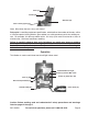
Welder Assembly Photographs 28 24 23 20 11 19 36 35 35 34 23 SKU 54878 For technical questions, please call 1-800-444-3353.
Wiring Schematic SKU 54878 For technical questions, please call 1-800-444-3353.
Warranty Limited 90 day/1 year warranty Harbor Freight Tools Co. makes every effort to assure that its products meet high quality and durability standards, and warrants to the original purchaser that for a period of ninety days from date of purchase that the torch, liner, wire feed mechanism (if applicable), welding clamps, electrode holders, cables and accessories packed with the welder are free of defects in materials and workmanship.