Wireless Access CONFIGURING & OPERATING INSTRUCTIONS SCHLAGE WIRELESS ACCESS SYSTEM (WAS) The most current version of this document is available for download at: http://www.ir-swa.
Wireless Access Schlage Ingersoll Rand Security Technologies 245 W. Roosevelt Road, Building 7, Suite 48 West Chicago, IL 60185 main: 800-313-2962 (630-876-5680) technical support: 866-322-1237 fax: 630-293-4257 web: ir-swa.com Copyright © 2003-2006 Ingersoll Rand, all rights reserved. No part of this document can be reproduced, transmitted, or transcribed in any form by electrical, mechanical, optical, manual, or otherwise without the prior written consent of Ingersoll Rand.
Wireless Access CONFIGURING & OPERATING INSTRUCTIONS NOTE: This manual is intended to be used after the Schlage Wireless Access Modules have been installed. Each Schlage Wireless Access module has its own installation manual. Use this manual to configure and operate your system. TABLE OF CONTENTS 1. 2. 3. 4. 5. 6. 7. Schlage Wireless Access System (WAS) ............................................................................................................6 Panel Interface Module (PIM)............
Wireless Access 7.2 Linking to the WPIM by Powering the WRI-IN..........................................................................................32 7.3 Testing the WRI-IN .....................................................................................................................................33 7.4 Re-linking a WRI-IN and WPIM.................................................................................................................34 7.5 Changing the RF Channel.......................
Wireless Access 12.7 Updating the WPR’s Firmware................................................................................................................55 13. Other Important Information.......................................................................................................................56 13.1 Knowing When to Change the RF Channel.............................................................................................56 13.2 Configuring the Schlage Wireless AccessTM System.....
Wireless Access 1. Schlage Wireless Access System (WAS) Every access control system that uses Schlage Wireless Access contains two different types of modules (Figure 1-1): • at least one Wireless Panel Interface Module (WPIM), and • at least one Schlage Wireless Access Point Module (WAPM) Figure 1-1 – Schlage Wireless Access System Block Diagram The Schlage Wireless Access product line contains several different expressions of each module (Table 1-1).
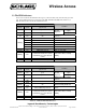
Wireless Access 2. Panel Interface Module (PIM) The Panel Interface Module (PIM) is a product in the Schlage Wireless Panel Interface Module (WPIM) category. The PIM is the wireless interface to an access control panel. Table 2-1 & Table 2-2 show the PIM sales models and their major specifications.
Wireless Access MODEL* ENCLOSURE MAXIMUM NUMBER OF WAPMs LOCATION PIM-TD2 plastic 2 indoor PIM-TD4 plastic 4 indoor PIM-485-OTD plastic 16 indoor PIM-EXP n/a 2 indoor ANT-REM-IN plastic n/a indoor ANT-REM-I/O plastic n/a ANT-REM-I/O+6DB plastic n/a indoor outdoor indoor outdoor ACCESS CONTROL PANEL INTERFACE/DESCRIPTION Magnetic (clock & data) or Wiegand (data1/data0) Magnetic (clock & data) or Wiegand (data1/data0) RS485 (OEM specific protocol) Magnetic (clock & data) or Wieg
Wireless Access Figure 2-1 – PIM-TD2 & PIM-EXP Printed Circuit Board (PCB) Figure 2-2 – PIM-485-OTD Printed Circuit Board (PCB) Ingersoll Rand Security Technologies 245 W. Roosevelt Road, Bldg 7, Suite 48, West Chicago, IL 60185 / (800) 313-2962 / (630) 293-4257 fax P/N: M053-007-D www.ir-swa.
Wireless Access 2.2 The PIM Indicators There are five LEDs on the PIM PCB: CR15 (green), CR7 and CR10 (red), CR6 and CR9 (green and red). These LEDs indicate the current status of the PIM-TD2/PIM-TD3/PIM-EXP (Table 2-3) or PIM-485-OTD (Table 2-4) and the WAPMs linked to it.
Wireless Access 2.3 How to Set an RF Channel First determine if you have a United States or Australian PIM: If your PIM model number is PIM-TD2, PIM-TD4, PIM-EXP, or PIM-485-OTD, then you have a United States PIM. Go to section 2.3.1. If your PIM model number is AUPIM-TD2, AUPIM-TD4, AUPIM-EXP, or AUPIM-485-OTD, then you have an Australian PIM. Go to section 2.3.2. 2.3.1 United States Version 2.3.1.
Wireless Access 2.3.1.2 United States Dynamic Channel Switching When using the United States version of Schlage Wireless Access products in the dynamic channel switching mode, one of five RF channel groups can be set using DIP switch SW7 on the PIM (Figure 2-1 or Figure 2-2).
Wireless Access 2.3.2 Australian Version 2.3.2.1 Australian Non Dynamic Channel Switching (default) When using the Australian version of Schlage Wireless Access products in the non dynamic channel switching mode, one of seven RF channels can be set using DIP switch SW7 on the PIM (Figure 2-1 or Figure 2-2).
Wireless Access 2.4 Putting the PIM-TD2, PIM-TD4 and PIM-EXP into Link Mode Note: To put a PIM-485-OTD into Link Mode the Configuration & Demonstration Tool (CDT) must be used. Refer to the appropriate PIM addendum manual for specific instructions. The Link Mode allows 2 WAPMs to be linked to a PIM-TD2 or PIM-EXP. The Link Mode allows 4 WAPM’s to be linked to a PIM-TD4. Only one WAPM can be linked at a time. 2.4.1 Once the RF Channel has been set (Section 2.
Wireless Access 2.8 Updating the PIM’s Firmware The PIM Programming Connector, J2 (Figure 2-1 or Figure 2-2) is used to install a new version of the PIM firmware into the PIM. If a new firmware version is required, please refer to the “Upgrading a WAPM or WPIM’s Firmware” application note, A664-010-x, available at www.ir-swa.com. Ingersoll Rand Security Technologies 245 W. Roosevelt Road, Bldg 7, Suite 48, West Chicago, IL 60185 / (800) 313-2962 / (630) 293-4257 fax P/N: M053-007-D www.ir-swa.
Wireless Access 3. Panel Interface Module Expander (PIM-EXP) The Panel Interface Module Expander (PIM-EXP) is a product in the Schlage Wireless Panel Interface Module (WPIM) category. The PIM-EXP installs in a PIM-TD2 enclosure and provides the ability to interface 1 or 2 additional Schlage Wireless Access Point Modules (WAPM) to an Access Control Panel. Figure 3-1 shows the PIM-TD2 enclosure with PIM-EXP installed. NOTE: A PIM-TD2 with a PIM-EXP installed is the same as a PIM-TD4.
Wireless Access 4. WA Series Integrated Lockset (WA5200 or WA5600) The WA Series Integrated Lockset is a product in the Schlage Wireless Access Point Module (WAPM) category. Cylindrical (WA5200) and mortise (WA5600) lockset versions are available. AUWA5200 and AUWA5600 are Australian versions of the WA series integrated locksets. Note: In this section, WA refers to a WA5200, a WA5600, an AUWA5200, or an AUWA5600.
Wireless Access 4.
Wireless Access 4.2 Linking a WA5200/WA5600 to a WPIM NOTE: Only one WAPM can be linked at a time. 4.2.1 If the WA does not have a Battery Pack installed, install one now (section 4.4). 4.2.2 Make certain that the WPIM to be linked to is in the Link Mode (Section 2.3.2). 4.2.3 To initiate the linking process: 4.2.3.1 Open the door. 4.2.3.2 Activate and hold down the inside lever to create a Request to Exit Condition. 4.2.3.
Wireless Access Figure 4-7 – WA Battery Pack (K380-001) 4.3 Testing a WA5200/WA5600 4.3.1 Proximity Card Reader Models 4.3.1.1 Place the card flat to and within 1 to 3 inches of the upper part of the Proximity Reader (Figure 4-8). The reader sounder beeps. NOTE: For HID iCLASS reader versions of the WA see section 13.5, page 57, below. Figure 4-8 - Presenting a Proximity Card to a WA 4.3.1.2 The green LED flashes and the lock will unlock. 4.3.1.3 Turn the Lever and open the door. 4.3.1.
Wireless Access 4.3.2.3 Turn the Lever and open the door. 4.3.2.4 Shortly after the green flash, there is a red flash and sounder beep signifying relock. 4.3.3 Indication of an Unsuccessful Card Read The best indication of an unsuccessful valid card read is when the WA’s internal sounder does not beep, indicating that the card was not read. If an invalid card is read, the WA’s red LED flashes twice and the internal sounder beeps once. In both cases the WA remains locked. 4.
Wireless Access out of Link Mode and put back into Link Mode for the new RF channel to be selected. The WPIM is taken out of Link Mode by pressing the switch associated with the Access Point that is in the Link Mode (S1 or S2). NOTE: Changing the RF channel will require all WAPMs linked to the PIM to be re-linked. 4.7 Updating the WA’s Firmware If a new firmware version is required, please refer to the “Upgrading a WAPM or WPIM’s Firmware” application note, A664-010-x, available at www.ir-swa.com.
Wireless Access 5. WA Exit Trim (WA993) The WA Exit Trim (WA993) is a product in the Schlage Wireless Access Point Module (WAPM) category. AUWA993 is an Australian version of the WA exit trim. Note: In this section, WA993 refers to either a WA993 or an AUWA993. Figure 5-1 – WA993 Locked Side (Outside) Figure 5-2 – WA993 Unlocked Side (Inside) 5.
Wireless Access 5.2 Linking the WA993 to a WPIM NOTE: Only one WA993 can be linked at a time. 5.2.1 If the WA993 does not have a Battery Pack installed, install one now (section 5.4). 5.2.2 Make certain that the WPIM to be linked to is in the Link Mode (Section 2.3.2). 5.2.3 To initiate the linking process: 5.2.3.1 Open the door. 5.2.3.2 Push the crash bar to create a Request to Exit condition. 5.2.3.
Wireless Access Figure 5-5 – WA993 Battery Pack (K380-001) 5.3 Testing the WA993 5.3.1 Proximity Card Reader Models 5.3.1.1 Place the card flat to and within 1 to 3 inches of the Proximity Reader (Figure 5-6). Figure 5-6 - Presenting a Proximity Card to a WA993 5.3.1.2 The green LED flashes and the lock will unlock. 5.3.1.3 Turn the Lever and open the door. 5.3.1.4 Shortly after the green flash, there is a red flash and sounder beep signifying relock. 5.3.2 Magnetic Stripe Reader Models 5.3.2.
Wireless Access 5.3.3 Indication of an Unsuccessful Card Read The best indication of an unsuccessful valid card read is when the WA993’s internal sounder does not beep, indicating that the card was not read. If an invalid card is read, the WA993’s red LED flashes twice and the internal sounder beeps once. In both cases the WA993 remains locked. 5.4 Installing/Replacing the WA993 Battery Pack (K380-001) NOTE: If you want to re-link when changing the WA993 Battery Pack, follow the procedure in section 5.
Wireless Access 6. Outdoor Wireless Reader Interface (WRI-OTD) The Outdoor Wireless Reader Interface (WRI-OTD-12VDC) is a product in the Schlage Wireless Access Point Module (WAPM) category. AUWRI-OTD-12VDC is an Australian version of the outdoor wireless reader interface. Note: In this section, WRI-OTD refers to either a WRI-OTD-12VDC or an AUWRI-OTD-12VDC.
Wireless Access 6.1 The WRI-OTD Visual Indicators There are two LEDs on the WRI-OTD PCB: a red Power LED (LED1, Figure 6-3) and a green/red State LED (LED2, Figure 6-3). These LEDs indicate the current status of the WRI-OTD (Table 6-1).
Wireless Access 6.2.2 Reset the WRI-OTD by either cycling the WRI-OTD power (J3, Figure 6-3) or by pressing and releasing the WRI-OTD Reset Switch (S1, Figure 6-3). After displaying the firmware version number on LED2, the WRI-OTD attempts to link with a WPIM. 6.2.
Wireless Access 6.3.4 Door Position Do this test if a Door Position device is wired to the WRI-OTD Portal Inputs (J7-5 & 6, Figure 6-3). Using either the Schlage Configuration and Demonstration Tool (CDT) or the Access Control Panel software (ACP Software), verify that the CDT or ACP software can monitor the door’s position by opening and closing the door. 6.3.5 Strike Relay Do this test if an electrical lock or load is connected to the WRI-OTD Strike Portal Output (J8-1, 2, and/or 3, Figure 6-3).
Wireless Access 7. Indoor Wireless Reader Interface (WRI-IN) The Wireless Reader Interface (WRI-IN) is a product in the Schlage Wireless Access Point Module (WAPM) category. AUWRI-IN-12VDC is an Australian version of the indoor wireless reader interface. Note: In this section, WRI-IN refers to either a WRI-IN-12VDC or an AUWRI-IN-12VDC. Figure 7-1 – Front of the WRI-IN Figure 7-2 – Inside the WRI-IN Figure 7-3 – WRI-IN Printed Circuit Board (PCB) Ingersoll Rand Security Technologies 245 W.
Wireless Access 7.1 The WRI-IN Visual Indicators Depending on how the Card Reader is interfaced to the WRI-IN, the LED on the Card Reader may display some WRI-IN status conditions (Table 7-1).
Wireless Access If the WRI-IN & WPIM determine that the RF signal quality is not acceptable then the link fails and the WRI-IN Card Reader LED may blink red twice (Table 7-1). The WPIM will stay in the Link Mode. If this happens, move either the WRI-IN, PIM, or change RF channels and try the link process again (Section 7.2.1). 7.2.5 Close and secure the WRI-IN enclosure cover. 7.2.6 The WRI-IN is now ready to be tested for normal operation. 7.
Wireless Access 7.3.5 Strike Relay Do this test if an electrical lock or load is connected to the Strike Portal Output (Figure 7-3). Using either the Schlage Configuration and Demonstration Tool (CDT) or the Access Control Panel software (ACP Software), verify that Strike Portal Output can control the electrical lock or load. 7.3.6 Card Reader Do this test if a card reader or keypad is connected to the Card Reader (Figure 7-3) connector.
Wireless Access 8. Wireless Portable Readers, Version 2 (WPR2) The Wireless Portable Reader, Version 2 (WPR2) is a product in the Schlage Wireless Access Point Module (WAPM) category (Figure 9-1 and Figure 9-2). AUWPR2 is an Australian version of the wireless portable reader. Note: In this section, WPR2 refers to either a WPR2 or an AUWPR2. Figure 9-1 – WPR2 with Proximity Reader Figure 9-2 -WPR2 with Magnetic Reader Figure 9-3 – Inside the WPR2 Ingersoll Rand Security Technologies 245 W.
Wireless Access 8.
Wireless Access 8.3.4 During linking, the WPIMs LED (CR6 or CR9, depending on the WPR2 being linked) blinks green (some intermittent red may be seen) and the WPR2 LED (Figure 9-1 or Figure 9-2) blinks green (some intermittent red may be seen) for about 20 seconds while the WPR2 & WPIM determine the integrity of the selected RF channel. 8.3.
Wireless Access Figure 9-4 – Battery Retainer Figure 9-5 – Disconnecting Battery Pack 8.5.3 Connect the new Battery Pack connector to the mating connector coming from the transceiver board (Figure 9-6). Figure 9-6 - Installing New Battery Pack 8.5.4 Carefully pack the battery wires, position the Battery Pack in its original location, and re-install the Battery Retainer (Figure 9-4). 8.5.
Wireless Access 9. Wireless Status Monitor (WSM) The Wireless Status Monitor (WSM) is a product in the Schlage Wireless Access Point Module (WAPM) category. AUWSM is an Australian version of the wireless status monitor. Note: In this section, WSM refers to either a WSM or an AUWSM. Figure 10-1 – Wireless Status Monitor Figure 10-2 – WSM Battery Pack (K380-001) Figure 10-3 – Transceiver Control Module with Cover Removed Ingersoll Rand Security Technologies 245 W.
Wireless Access 9.1 The WSM Visual Indicators NOTE: LED assembly must be installed on the GRN_LED & RED_LED connections of J3 in order for any visual indicators to be seen (see Fig. 10-3).
Wireless Access 9.2.6 Re-install the WSM cover, making certain that no wires are pinched. The cover should go on easy with no interferences. Replace the 4 cover screws, one in each corner (Figure 10-1). 9.2.7 The WSM is now ready for normal operation. 9.3 Replacing the WSM Battery Pack, K380-001 Approximately one month prior the end of the WSM’s Battery Pack life, a Low Battery Trouble signal is indicated at the WPIM (Table 2-4), a Trouble signal will be sent to the access control panel.
Wireless Access 9.4 Re-linking an WSM and WPIM To re-link a WSM and WPIM follow the instructions in Section 9.1. 9.5 Changing the RF Channel At the WPIM, change DIP switch SW7 to the desired new RF channel (Section 2.3), place the PIM in Link Mode (see Section 2.3.2), then re-link the desired WSM (Section 9.4). NOTE: The WPIMs RF channel DIP switch (SW7) is read when the WPIM enters the Link Mode.
Wireless Access 10. Modular Integrated Reader Lock (MIRL) The Modular Integrated Reader Lock (MIRL) is a product in the Schlage Wireless Access Point Module (WAPM) category. Figure 10-1 – MIRL Locked Side (Outside) Figure 10-2 – MIRL Unlocked Side (Inside) 10.
Wireless Access 10.2 Linking the MIRL to a WPIM NOTE: Only one WAPM can be linked at a time. 10.2.1 If the MIRL does not have a Battery Pack installed, install one now (section 4.4). 10.2.2 Make certain that the WPIM to be linked to is in the Link Mode (Section 2.3.2). 10.2.3 To initiate the linking process: 10.2.3.1 Open the door. 10.2.3.2 Activate and hold down the inside lever to create a Request to Exit Condition. 10.2.3.
Wireless Access Figure 10-5 – MIRL Battery Pack (K380-001) 10.3 Testing the MIRL 10.3.1 Proximity Card Reader Models 10.3.1.1 Place the card flat to and within 1 to 3 inches of the upper part of the Proximity Reader (Figure 4-8). The reader sounder beeps. NOTE: For HID iCLASS reader versions of the MIRL see section 13.5, page 57, below. Figure 10-6 - Presenting a Proximity Card 10.3.1.2 The green LED flashes and the lock will unlock. 10.3.1.3 Turn the Lever and open the door. 10.3.1.
Wireless Access 10.4 Installing/Replacing the MIRL Battery Pack (K380-001) Approximately one month prior the end of the MIRL Battery Pack life, a Low Battery Trouble signal is indicated at the WPIM (Table 2-4) and a Trouble signal will be sent to the access control panel. To install or replace the MIRL Battery Pack, remove the MIRL Transceiver Cover (Figure 4-5). IF replacing, disconnect the old MIRL Battery Pack. If installed, remove the Battery Bracket.
Wireless Access 11. Wireless Exit Trim Kit (WEXK) The Wireless Exit Trim Kit (WEXK) is a product in the Schlage Wireless Access Point Module (WAPM) category. Figure 11-1 – WEXK Locked Side (Outside) Figure 11-2 – WEXK Unlocked Side (Inside) Ingersoll Rand Security Technologies 245 W. Roosevelt Road, Bldg 7, Suite 48, West Chicago, IL 60185 / (800) 313-2962 / (630) 293-4257 fax P/N: M053-007-D www.ir-swa.
Wireless Access 11.
Wireless Access 11.2.4 During linking, the WPIM’s LED (CR6 or CR9, depending on the door being linked) and the WEXK LED blink green (some intermittent red may be seen) for about 20 seconds while the WEXK & WPIM determine the integrity of the selected RF channel. 11.2.5 If the WEXK & WPIM determine that the RF channel can be used, then the linking is completed successfully and the WPIMs LED (CR6 or CR9, whichever was flashing) turns solid green. The WEXK LED then blinks green and the sounder beeps.
Wireless Access Figure 11-6 - Presenting a Proximity Card 11.3.1.2 The green LED flashes and the lock will unlock. 11.3.1.3 Turn the Lever and open the door. 11.3.1.4 Shortly after the green flash, there is a red flash and sounder beep signifying relock. 11.3.2 Magnetic Stripe Reader Models 11.3.2.1 Place the card at the top of the Magnetic Stripe Reader. The card’s magnetic stripe should be facing towards the right and the long edge of the card should be facing the door.
Wireless Access NOTE: If the Card Reader Base Plate has a Tamper Switch that is activated when the Reader Cover is removed, then the Card Reader is disabled. Tamper Switch must be manually held closed (simulating the cover being installed) for the Card Reader to operate. Figure 11-7 – WEXK Battery Override 11.6 Re-linking a WEXK and WPIM To re-link a WEXK and WPIM, follow the instructions in Section 5.2. 11.
Wireless Access 12. Wireless Portable Readers (WPR) The Wireless Portable Reader (WPR) is a product in the Schlage Wireless Access Point Module (WAPM) category (Figure 8-1). Figure 8-1 – Wireless Portable Reader (WPR) with Proximity Reader 12.
Wireless Access 12.2 Turning the WPR On The WPR is turned On & Off using the On/Off switch located on the WPR cover (Figure 8-1). When the WPR is turned on, Action 1, Table 8-12-1 occurs. Actions 2a, 2b, 2c, and/or 2d will only occur if the WPR is being linked (Section 12.3). 12.3 Linking or Re-Linking to the WPIM by Powering the WPR NOTE: Only one WAPM can be linked at a time. 12.3.1 Make certain that that WPIM to be linked to is in the Link Mode (Section 2.3.2). 12.3.
Wireless Access 12.4.2 Proximity Card Reader Models 12.4.2.1 Place a valid card flat to and within 1 to 3 inches of the upper part of the Proximity Reader. The reader sounder beeps. 12.4.2.2 The green LED will flash when a valid card is read. 12.4.3 Indication of an Unsuccessful Card Read The best indication of an unsuccessful valid card read is when the WPR’s internal sounder does not beep, indicating that the card was not read correctly.
Wireless Access 12.5.5 To continue to use the WPR on the same RF channel and with the same WPIM, re-install the cover, making certain that no wires are pinched. The cover should go on easy with no interferences. Replace the 4 cover screws, one in each corner (Figure 8-1). If the WPR needs to be re-linked or the RF channel needs to be changed, before re-installing the WPR cover, follow the instructions in Section 12.2 or Section 12.6. 12.
Wireless Access 13. Other Important Information 13.1 Knowing When to Change the RF Channel The RF Channel should be changed if the system encounters interfering transmissions (most noticeably when the system attempts to Link and cannot or when a card swipe results in a “no communication” indication at the Access Point). Try re-linking on a different RF channel. If the WAPM and WPIM do not re-link on the new channel, try another channel.
Wireless Access Note: The exact time that the Access Point will be unlocked or locked depends on the frequency of RF activity between the WAPM and the WPIM. Generally the WAPM is in a low power mode (i.e. sleeping) and therefore the WPIM can only communicate with the WAPM when the WAPM initiates the communication. The Heartbeat time will determine the maximum time that it will take for a WAPM to respond to the start or end of an extended unlock.
Wireless Access 14. Contacting Technical Support For questions regarding Schlage Wireless Access: www.ir-swa.com main: 800-313-2962 (630-876-5680) technical support: 866-322-1237 fax: 630-293-4257 Ingersoll Rand Security Technologies 245 W. Roosevelt Road, Bldg 7, Suite 48, West Chicago, IL 60185 / (800) 313-2962 / (630) 293-4257 fax P/N: M053-007-D www.ir-swa.
Wireless Access 15. FCC Compliance, ACA Compliance, & Warnings 15.1 FCC Compliance • The United States and Canada versions of these devices have been authorized by the FCC Rules and Industry Canada for use in the United States and Canada. • This device complies with the limits for a Class B digital device and a Class B intentional radiator, pursuant to Part 15 of the FCC Rules and with RSS-210 of Industry Canada.
Wireless Access 16. Revision History Version X1.0 001 X02 Date 11/12/01 11/15/01 11/20/01 002 X03.0 003 11/27/01 12/14/01 12/18/01 004 02/27/02 005 05/23/02 006 06/10/02 x007 007 10/31/02 11/05/02 x008 x008.