9” ANGLE GRINDER Model 93179 Set up and Operating Instructions Visit our website at: http://www.harborfreight.com Read this material before using this product. Failure to do so can result in serious injury. Save this manual. Copyright© 2005 by Harbor Freight Tools®. All rights reserved. No portion of this manual or any artwork contained herein may be reproduced in any shape or form without the express written consent of Harbor Freight Tools. Diagrams within this manual may not be drawn proportionally.
such as pipes, radiators, ranges, and refrigerators. There is an increased risk of electric shock if your body is grounded. Save This Manual You will need the manual for the safety warnings and precautions, assembly instructions, operating and maintenance procedures, parts list and diagram. Keep your invoice with this manual. Write the invoice number on the inside of the front cover. Keep the manual and invoice in a safe and dry place for future reference. Safety Warnings and Precautions 7.
activities, contain chemicals known (to the State of California) to cause cancer, birth defects or other reproductive harm. Some examples of these chemicals are: lead from lead-based paints, crystalline silica from bricks and cement or other masonry products, arsenic and chromium from chemically treated lumber. Your risk from these exposures varies, depending on how often you do this type of work.
10. Never leave the tool unattended when it is plugged into an electrical outlet. Turn off the tool, and unplug it from its electrical outlet before leaving. Double Insulated Tools: Tools with Two Prong Plugs 11. Use only 9” diameter grinding wheels having a 5/8” or ( 7/8” if using included arbor adaptor) center mounting hole. Never disable or modify the wheel guard. 12. WARNING! Never install a carbide tipped or steel circular saw blade for use in this tool.
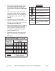
4. 5. 6. When using more than one extension cord to make up the total length, make sure each cord contains at least the minimum wire size required. (See Table A.) If you are using one extension cord for more than one tool, add the nameplate amperes and use the sum to determine the required minimum cord size. (See Table A.) If you are using an extension cord outdoors, make sure it is marked with the suffix “W-A” (“W” in Canada) to indicate it is acceptable for outdoor use. 7.
Specifications Input 120 V~, 60 Hz, 15 A Motor Speed 6500 RPM Power Cord 82”L x 14AWG 2 prong polarized Construction Molded ABS Motor Housing Cast Aluminum Gear Housing Wheel Diameter 9” with 5/8” x 11TPI Arbor Spindle optional 7/8” Arbor Adaptor included Overall Dimensions 18-1/2”L x 4-3/8”W x 5-1/2”H Tighten the Screw (5) in the Guard Clamp (4) Unpacking When unpacking, check to make sure that the product is intact and undamaged.
You must install the Grinding Wheel (502) before using your tool. 1. Place the Backing Washer (2) on the Arbor Spindle (7) as shown, making sure it fits tight. 2. Place the Grinding Wheel (502) on top of the Backing Washer (2), making sure the bore of the Grinding Wheel fits onto the step of the Arbor Spindle (7). 3. Place the Disc Locking Nut (1) onto the Arbor Spindle (7) with the concave recessed side against the Grinding Wheel (502). 4. Press in and hold the Spindle Lock (22).
Using the Angle Grinder Rotating the Back Handle Before using the Angle Grinder, be sure all work area safety precautions are being observed. Be sure to wear ANSI approved eye protection. WARNING: Always use 2 hands during use. Rotating the Back Handle You can rotate the Back Handle (41, 48) by pressing the Rotation Button (53). 1. First unplug the tool. 2. Hold the Main Body of the tool with one hand. With the other grip the Back Handle and press in the Rotation Button. 3.
Maintenance and Inspection 1. The Armature (31) and Stator (36) comprise the main part of the tool. Protect these electrical components from moisture or oil intrusion. 2. Inspect the Carbon Brushes (50) regularly. Replace them is they are more than 1/3 worn or are chipped or cracked. When handling them, be careful not to damage them. To reduce wear after inspection, replace them in exactly the same way as they were removed. 3.
Parts List PART 1 2 3 4 5 6 7 8 9 10 11 12 13 14 15 16 17 18 19 20 21 22 23 24 25 26 27 DESCRIPTION Disc Locking Nut Backing Washer Wheel Guard Guard Clamp Screw M8x28 Key 4x5x13 Arbor Spindle Screw M5x16 Spring Washer *5 Gear Housing Cover Ball Bearing 6202RS Bearing Cover Screw M4x10 Spring Washer *4 Big Gear Circlip for Shaft *15 Bronze Bushing Screw ST5x45 Gear Housing “E” Ring Spindle Lock Spring Spindle Lock Rubber Plug Side Handle Nut M8x1 Pinion Ball Bearing 6202RS PART 29 30 31 32 33 34 35 36 37
Assembly Drawing SKU 93179 For technical questions, please call 1-800-444-3353.
LIMITED 90 DAY WARRANTY Harbor Freight Tools Co. makes every effort to assure that its products meet high quality and durability standards, and warrants to the original purchaser that this product is free from defects in materials and workmanship for the period of 90 days from the date of purchase.