2.5 Horsepower industrial breaker hammer kit Model 96035 Set up and Operating Instructions Visit our website at: http://www.harborfreight.com Read this material before using this product. Failure to do so can result in serious injury. Save this manual. Copyright© 2007 by Harbor Freight Tools®. All rights reserved. No portion of this manual or any artwork contained herein may be reproduced in any shape or form without the express written consent of Harbor Freight Tools.
NOTICE is used to address practices not related to personal injury. Save This Manual Keep this manual for the safety warnings and precautions, assembly, operating, inspection, maintenance and cleaning procedures. Write the product’s serial number in the back of the manual near the assembly diagram (or month and year of purchase if product has no number). Keep this manual and the receipt in a safe and dry place for future reference.
a power tool will increase the risk of electric shock. d. Do not overreach. Keep proper footing and balance at all times. This enables better control of the power tool in unexpected situations. c. Do not abuse the cord. Never use the cord for carrying, pulling or unplugging the power tool. Keep cord away from heat, oil, sharp edges or moving parts. Damaged or entangled cords increase the risk of electric shock. e. Dress properly. Do not wear loose clothing or jewelry.
e. Maintain power tools. Check for misalignment or binding of moving parts, breakage of parts and any other condition that may affect the power tool’s operation. If damaged, have the power tool repaired before use. Many accidents are caused by poorly maintained power tools. f. Keep cutting tools sharp and clean. Properly maintained cutting tools with sharp cutting edges are less likely to bind and are easier to control. g. Use the power tool, accessories and tool Chisels etc.
chemicals known [to the State of California] to cause cancer, birth defects or other reproductive harm. Some examples of these chemicals are: • Lead from lead-based paints • Crystalline silica from bricks and cement or other masonry products • Arsenic and chromium from chemically treated lumber Your risk from these exposures varies, depending on how often you do this type of work.
Grounding To prevent electric shock and death from incorrect grounding wire connection: Check with a qualified electrician if you are in doubt as to whether the outlet is properly grounded. Do not modify the power cord plug provided with the tool. Never remove the grounding prong from the plug. Do not use the tool if the power cord or plug is damaged. If damaged, have it repaired by a service facility before use. If the plug will not fit the outlet, have a proper outlet installed by a qualified electrician.
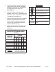
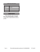
Symbology Double Insulated Canadian Standards Association Underwriters Laboratories, Inc. V~ A Volts Alternating Current Amperes No Load Revolutions per Minute n0 xxxx/min. (RPM) Protect the extension cords from sharp objects, excessive heat, and damp or wet areas. RECOMMENDED MINIMUM WIRE GAUGE FOR EXTENSION CORDS* (120 VOLT) EXTENSION CORD LENGTH (at full load) 150’ NAMEPLATE AMPERES 100’ 8. Make sure the extension cord is properly wired and in good electrical condition.
Specifications Electrical Input 120 V~ / 60 Hz / 15 A Blows Per Minute 1030 BPM Tool Mount Spring-Loaded Rotational Lock Chisel 1 Bull Point (Included) Weight 77 lb. Unpacking When unpacking, make sure that the item is intact and undamaged. If any parts are missing or broken, please call Harbor Freight Tools at 1-800-444-3353 as soon as possible. Page 8 For technical questions, please call 1-800-444-3353.
Instructions for putting into use Read the entire Important Safety Information section at the beginning of this manual including all text under subheadings therein before set up or use of this product. Left Handle (92) Right Handle (89) Figure B 2. To prevent serious injury from accidental operation: Release the Trigger and unplug the tool from its electrical outlet before assembling or making any adjustments to the tool.
Installing a Chisel Figure 1A Chisels come with or without collars. Figure 1 shows installation of a chisel without a collar (the included chisel is without a collar). Figure 2 shows installation of a chisel with a collar. Note: If the Chisel doesn’t slide in easily, apply some grease on the loading end of the Chisel. Retaining Ring 2. Position the retaining ring as shown in Figure 1 and in Figure 1A. Then insert the Chisel with the flat on top of the receiver, as shown. 3.
With a Collar: Figure 2 Retaining Ring 1. Pull the retaining ring open about 3040° to the second engaging position as shown in Figure 2. 2. Insert the collared chisel. 3. Return the retaining ring to its original position to lock the chisel in place. Physically check that the chisel is secure before operating. The chisel will have approximately 1-3/4” of play, but should not come out when pulled. SKU 96035 For technical questions, please call 1-800-444-3353.
Operating Instructions Read the entire Important Safety Information section at the beginning of this manual including all text under subheadings therein before set up or use of this product. Work Piece and Work Area Set Up 1. Designate a work area that is clean and well-lit. The work area must not allow access by children or pets to prevent distraction and injury. 2.
1. Clearly mark the work area. 2. Plug in the Breaker Hammer. 3. Place the Chisel on the block you will be breaking. NOTE: Carbon Brushes (51) will wear during use. The Breaker Hammer will cease functioning if the Brushes are worn. This does NOT mean Breaker Hammer is malfunctioning or broken, only that the worn Brushes will need to be replaced with the included Brushes by a qualified technician. 4. 5.
Figure 3 Screws (25) Left Handle (92) Gearbox (23) Nut (91) Figure 8 5. Figure 6 3. Remove the four Screws (25) from the side of the Gearbox 23. See Figure 8. Use a Wrench to loosen the Nut (91) holding the Left Handle (92) in place. See Figure 6. Figure 7 Spline Axle (27) Wire Board (50) Left Handle (92) Screw (52) Figure 9 4. CAUTION: When removing Left Handle, do not pull too far from Spline Axle (27) Only wiggle loose until partially off. See Figure 7. Page 14 6.
Carbon Brush Holder Spring Carbon Brush (52) Carbon Brush Holder (53) Housing Slot Wire Fixing Board (50) Gearbox Tab Figure 11 Figure 10 7. Remove the Wire Board from the top of the Carbon Brush Holder (53). Then use tip of flat-edge screwdriver (not included) to carefully pop the Holder’s spring off the top of the Carbon Brush (51). See Figure 10. 8. CAUTION! The spring must be clear of the Holder lip to remove Carbon Brush. 9. Use the screwdriver to slide the Carbon Brush from the Holder.
Maintenance And Servicing Procedures not specifically explained in this manual must be performed only by a qualified technician. To prevent serious injury from accidental operation: Release the Trigger and unplug the tool from its electrical outlet before performing any inspection, maintenance, or cleaning procedures. 5. Add a drop or two of a lightweight oil to the Trigger assembly area to lubricate the Trigger (86). 6. Examine the tool before each use.
Troubleshooting Problem Tool will not start. Possible Causes 1. Cord not connected. 2. No power at outlet. Likely Solutions 1. Check that cord is plugged in. 2. Check power at outlet. If outlet is unpowered, turn off tool and check circuit breaker. If breaker is tripped, make sure circuit is right capacity for tool and circuit has no other loads. 3. Turn off tool and allow to cool. Press reset button on tool. 4. Have technician service tool. 3. Tool’s thermal reset breaker tripped (if equipped). 4.
PLEASE READ THE FOLLOWING CAREFULLY The manufacturer and/or distributor has provided the parts list and assembly diagram in this manual as a reference tool only. Neither the manufacturer or distributor makes any representation or warranty of any kind to the buyer that he or she is qualified to make any repairs to the product, or that he or she is qualified to replace any parts of the product.
Assembly Drawing 27 26 25 24 23 22 1 2 14 13 93 17 56 92 91 16 57 21 3 15 58 44 59 96 30 19 18 45 60 29 20 31 32 33 46 61 4 47 34 5 48 49 62 63 11 50 39 38 37 35 36 6 40 12 51 41 64 7 65 70 8 52 54 71 53 55 72 73 74 66 67 80 76 10 81 82 83 84 75 68 9 79 88 87 43 42 85 69 77 86 78 89 90 SKU 96035 For technical questions, please call 1-800-444-3353.
Record Product’s Serial Number Here: To take advantage of this warranty, the product or part must be returned to us Note: If product has no serial number, record with transportation charges prepaid. Proof of purchase date and an explanation of the month and year of purchase instead. complaint must accompany the merchandise.