2.5 hp 1,000 watt ohv generator Model 97906 Set up, Operating, and Servicing Instructions Using an engine indoors CAN KILL YOU IN MINUTES. Engine exhaust contains carbon monoxide. This is a poison you cannot see or smell. NEVER use inside a home or garage, EVEN IF doors and windows are open. Only use OUTSIDE and far away from windows, doors, and vents. Diagrams within this manual may not be drawn proportionally.
Contents Important SAFETY Information ���������������������������� 3 Set up ������������������������������������������ 6 Operation ���������������������������������� 6 Service ��������������������������������������� 7 Basic Specifications ������������� 8 Unpacking ���������������������������������� 8 Set Up Instructions ��������������� 8 Location ������������������������������������������ 9 Grounding �������������������������������������� 9 Operating Instructions ������ 9 Engine Controls ����������������
Save This Manual NOTICE is used to address practices not related to personal injury. Keep this manual for the safety warnings and precautions, assembly, operating, inspection, maintenance and cleaning procedures. Write the product’s serial number in the back of the manual near the assembly diagram (or month and year of purchase if product has no number). Keep this manual and the receipt in a safe and dry place for future reference.
5. Wear ANSI-approved safety goggles, heavy-duty work gloves, and dust mask/respirator during set up. 6. Use only oil and fuel recommended in the “Specifications” section of this manual. Operating precautions 1. Carbon Monoxide Hazard Using an engine indoors CAN KILL YOU IN MINUTES. Engine exhaust contains carbon monoxide. This is a poison you cannot see or smell. 5. People with pacemakers should consult their physician(s) before use.
13. Keep the equipment, engine, and surrounding area clean at all times. 14. Use the equipment, accessories, etc., in accordance with these instructions and in the manner intended for the particular type of equipment, taking into account the working conditions and the work to be performed. Use of the equipment for operations different from those intended could result in a hazardous situation. 15. Do not operate the equipment with known leaks in the engine’s fuel system. 16.
of battery without a proper regulating device. 7. Have the equipment serviced by a qualified repair person using only identical replacement parts. This will ensure that the safety of the equipment is maintained. Do not attempt any service or maintenance procedures not explained in this manual or any procedures that you are uncertain about your ability to perform safely or correctly. 8. Store equipment out of the reach of children. 9. Follow scheduled engine and equipment maintenance. 10.
2. Do not touch electrically energized parts of the Generator and interconnecting cables or conductors with any part of the body, or with any non-insulated conductive object. 3. Use only Class BC or Class ABC fire extinguishers on electrical fires. 4. Do not overload the generator. Overloading can cause fires in the electrical cords, in addition to generator and appliance damage. Service 1. Keep all electrical equipment clean and dry. Replace any wiring where the insulation is damaged.
Basic Specifications Fuel Engine Oil Type 89+ octane unleaded gasoline Capacity 1.05 Gallons Type SAE 10W30 (above 32° F) SAE 5W30 (at 32° F or below) Capacity 0.42 Quarts Horsepower 2.5 HP Run Time @ 50% Load 4 Hours, 20 Minutes with full tank Sound Level 65 dB AC Output (2) 120 V~, 60 hz 1,000 W Rated 1,050 W Peak DC Output 16.8V to 17.2V Note: Additional specifications found in the Technical Engine Specifications chart in this manual.
Location 1. 2. The Generator must be installed outdoors where ventilation is readily available. tion must be completed by a licensed contractor. Operating Instructions Read the entire Important Safety Information section at the beginning of this manual including all text under subheadings therein before set up or use of this product. Install the Generator so that the air inlets and outlets are not blocked by obstructions such as bushes, trees, or snow drifts.
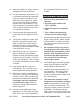
Circuit Protectors Power DC (59a) Switch (52a) AC (53a) AC Outlets (54a) Pilot Lamp (56a) Oil Drain Plug oil level should be between the high and low marks on the dipstick. 3. If the oil level is below the low mark add the appropriate type of oil until the oil level is between the high and the low marks. Oil type: 32° F or above = SAE 10W30 Below 32° F = SAE 5W30 4. Replace the Oil Dipstick. CAUTION! Do not run the engine with too little or too much oil. The engine will be permanently damaged.
Start Procedure Before starting the engine: a. Follow the Set Up Instructions to prepare the equipment. b. Inspect the equipment and engine. c. Fill the engine with the proper amount and type of fuel and oil. d. Read the Equipment Operation section that follows. 1. 2. Break-in Period 1. Breaking-in the engine will help to ensure proper equipment and engine operation, and will extend the engine’s lifespan. The warranty is void if the engine is not broken in properly.
ment into the 110/120 volt AC Outlets (54a). The Generator has an AC Circuit Protector (53a) to protect the unit in case of an overload. If an overload occurs, the Breaker will switch to its “OFF” position and cause the Generator to shut down. Press the Circuit Protector button (53a) to reset the Generator. 3. When finished using the Generator, turn the Power Switch (52a) to its “OFF” position. Turn the Fuel Valves (9a) to their “OFF” positions.
Technical Specifications Engine Type Bore x Stroke Compression Ratio Displacement Rotation viewed from PTO (power takeoff - the output shaft) Type Fuel Capacity Engine Oil Type Capacity Spark Plug Valve Clearance Speed Type Gap Intake Exhaust Maximum Shaft size/type 4 Stroke OHV 52 x 38 mm 7.8:1 79cc Counterclockwise 89+ octane unleaded gasoline 1.05 Gallons SAE 10W30 (above 32° F) SAE 5W30 (at 32° F or below) 0.42 Quarts E6TC DENSO-W2OFP-U 0.6 - 0.7mm 0.15mm 0.
To prevent serious injury from equipment failure: Do not use damaged equipment. If abnormal noise, vibration, or excess smoking occurs, have the problem corrected before further use. Air Filter Element Maintenance 1. Wipe off the air cleaner cover. 2. The air cleaner cover is held in place by a wing nut or clamps. Remove it. 3. Remove the air filter element. 4.
4. 5. 6. If the electrode has deposits on it, polish it using emery paper. If the white insulator is cracked or chipped, the spark plug needs to be replaced. 4. Take note of the fuel filter’s orientation. 5. Place a suitable container under the fuel filter. When installing a new spark plug, adjust the plug’s gap to the specification on the Technical specification chart. Do not pry against the electrode or the insulator, the spark plug can be damaged. 6.
After Initial 20 Operation Hour Period: the carburetor. Wait for engine to cool before proceeding. a. Change engine oil. c. Clean out area around spark plug. Remove spark plug and pour one tablespoon of engine oil into cylinder through spark plug hole. Every 25 Operation Hours Thereafter: a. Clean/replace air filter element. b. Inspect/clean spark plug. d. Reinstall spark plug, but leave spark plug wire disconnected. Every 50 Operation Hours: e. Pull recoil starter to distribute oil in cylinder.
Troubleshooting Problem Engine will not start Possible Causes Fuel Related: 1. No fuel in tank or fuel valve closed. 2. Choke not in start position, especially with cold engine. 3. Low quality or deteriorated, old gasoline. 4. Carburetor not primed. Probable Solutions Fuel Related: 1. Fill fuel tank and open fuel valve. 2. Move choke to start position if engine is cold. 3. Use only fresh 89+ octane unleaded gasoline. 4. Prime carburetor by pressing priming bulb specified number of times (if equipped).
Troubleshooting Problem Engine misfires Possible Causes 1. Spark plug wire loose. 2. Incorrect spark plug gap or damaged spark plug. 3. Defective spark plug wire. 4. Old or low quality gasoline. 5. Incorrect compression. Engine stops suddenly 1. Low oil shutdown. Engine knocks Engine backfires Probable Solutions 1. Check wire connections. 2. Re-gap or replace spark plug. 3. Replace spark plug wire. 4. Use only fresh 89+ octane unleaded gasoline. 5. Diagnose and repair compression.
PLEASE READ THE FOLLOWING CAREFULLY The manufacturer and/or distributor has provided the parts list and assembly diagram in this manual as a reference tool only. Neither the manufacturer or distributor makes any representation or warranty of any kind to the buyer that he or she is qualified to make any repairs to the product, or that he or she is qualified to replace any parts of the product.
ASSEMBLY DIAGRAM REV 09b SKU 97906 For technical questions, please call 1-800-444-3353.
Part 1 2 3 4 5 6 7 8 9 10 11 12 13 14 15 16 17 18 19 20 21 22 23 24 25 26 27 28 29 30 31 32 33 34 35 36 37 38 39 40 41 42 43 44 45 46 47 48 49 50 51 52 53 Engine PARTS LIST Description Flange Bolt M6x12 Head Cover Apron Plate Breather Tube Head Cover Packing Flange Bolt M8x55 Flange Bolt M8x55 Flange Bolt M6x16 Flange Bolt M6x16 Rocker Assembly Exhaust Valve Spring Retainer Intake Valve Spring Retainer Valve Spring Apron Plate Push Rod Push Rod Cylinder Head Carburetor Stud Bolt Intake Pipe Gasket Carbur
Engine diagram SKU 97906 For technical questions, please call 1-800-444-3353.
Limited 1 year / 90 Day warranty Harbor Freight Tools Co. makes every effort to assure that its products meet high quality and durability standards, and warrants to the original purchaser that for a period of ninety days from date of purchase that the engine/motor, the belts (if so equipped), and the blades (if so equipped) are free of defects in materials and workmanship.
Owner’s Warranty Responsibilities • As the engine owner, you are responsible for the performance of the required maintenance listed in your Owner’s Manual. HFT recommends that you retain all receipts covering maintenance on your engine, but HFT cannot deny warranty solely for the lack of receipts or for your failure to ensure the performance of all scheduled maintenance.