8 VOLT CORDLESS DRILL Model 95848 OPERATING INSTRUCTIONS Due to continuing improvements, actual product may differ slightly from the product described herein. ® 3491 Mission Oaks Blvd., Camarillo, CA 93011 Visit our Web site at: http://www.harborfreight.com To prevent serious injury, Read and understand all warnings and instructions before use. Copyright© 2007 by Harbor Freight Tools®. All rights reserved.
Product Specifications Power Source 18 VDC, 1.3Ah, NiCd Battery Charge Time 1 Hour Charger Input 120 VAC / 60 Hz / 1.8A Chuck Type 1/2” Single Sleeve Keyless Torque Settings 16 Variable Speed 0-900 RPM Maximum Torque 6 ft./lb. Reversible Yes Trigger Lock Yes Weight 5.5 Pounds Save This Manual You will need this manual for the safety warnings and precautions, assembly, operating, inspection, maintenance and cleaning procedures, parts list and assembly diagram.
prong or modify the plug in any way. Do not use any adapter plugs. Check with a qualified electrician if you are in doubt as to whether the outlet is properly grounded. If the tools should electrically malfunction or break down, grounding provides a low resistance path to carry electricity away from the user. 2. Double insulated tools are equipped with a polarized plug (one blade is wider than the other). This plug will fit in a polarized outlet only one way.
Tool Use and Care 1. Use clamps (not included) or other practical ways to secure and support the workpiece to a stable platform. Holding the work by hand or against your body is unstable and may lead to loss of control. 2. Do not force the tool. Use the correct tool for your application. The correct tool will do the job better and safer at the rate for which it is designed. 3. Do not use the power tool if the trigger does not operate it.
areas near flammable chemicals, dusts, and vapors. Do not use this product in a damp or wet location. 2. Maintain labels and nameplates on the Cordless Drill. These carry important information. If unreadable or missing, contact Harbor Freight Tools for a replacement. 3. When using the Cordless Drill, always maintain a firm grip on the tool with both hands. 4. Hold the tool by its insulated gripping surfaces when performing an operation where the Cordless Drill may contact hidden wiring.
designed to filter out microscopic particles. (California Health & Safety Code § 25249.5, et seq.) 13. WARNING! People with pacemakers should consult their physician(s) before using this product. Operation of electrical equipment in close proximity to a heart pacemaker could cause interference or failure of the pacemaker. GROUNDING WARNING! Improperly connecting the grounding wire can result in the risk of electric shock.
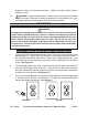
Double Insulated Tools: Tools With Two Prong Plugs 1. Tools marked “Double Insulated” do not require grounding. They have a special double insulation system which satisfies OSHA requirements and complies with the applicable standards of Underwriters Laboratories, Inc., the Canadian Standard Association, and the National Electrical Code. (See Figure B.) 2. Double insulated tools may be used in either of the 120 volt outlets shown in the preceding illustration. (See Figure B.) Extension Cords 1.
RECOMMENDED MINIMUM WIRE GAUGE FOR EXTENSION CORDS* (120 or 240 VOLT) NAMEPLATE AMPERES EXTENSION CORD LENGTH (at full load) 25 Feet 50 Feet 75 Feet 100 Feet 150 Feet 0 – 2.0 18 18 18 18 16 2.1 – 3.4 18 18 18 16 14 3.5 – 5.0 18 18 16 14 12 5.1 – 7.0 18 16 14 12 12 7.1 – 12.0 18 14 12 10 - 12.1 – 16.0 14 12 10 - - 16.1 – 20.0 12 10 - - - FIGURE C * Based on limiting the line voltage drop to five volts at 150% of the rated amperes.
UNPACKING When unpacking, check to make sure that the product is complete and undamaged. If any parts are missing or broken, please call Harbor Freight Tools at the number shown on the cover of this manual as soon as possible. Charging 1. NOTE: The Battery Pack (28) requires charging before first use. The first charge requires a one and a half hour charge prior to initial use of the Cordless Drill. 2. Note: Always switch to a fresh battery when tool performance begins to diminish.
OPERATING INSTRUCTIONS NOTE: For additional information regarding the parts listed in the following pages, refer to the Assembly Diagram on page 13. WARNING! Remove the Battery (28) from the tool and set the Rotation Button (9) to its center, locked, position before making any adjustments, changing accessories, or storing the tool. Accessory Grip (14) Torque Indicator Arrow Rotation Button (9) Chuck (16) Torque Setting Ring (15) Trigger (10) 2-Head Bit (3) Battery Pack (28) 1. 2. Figure E.
to prevent damage to the screw, bit, or workpiece. The higher the number, the more torque is applied before the clutch slips. Unless you are drilling, always start with a lower number to help prevent damage. This drill also has torque settings between the numbers to allow a greater range of control. Drill Setting ( ): This setting essentially prevents the clutch from slipping entirely.
Drill only as deep as necessary. Do not drill deeper than necessary into walls or other areas where you cannot identify any possible hazards behind the drilling surface. To reduce jamming as the Bit breaks through the workpiece, decrease the drilling pressure when the point of the Bit breaks through the workpiece. 14. When you have drilled the hole, remove the Bit from the hole while the Cordless Drill is still running. This prevents the Bit from getting caught in the hole and causing damage. 15.
Parts list Part Description QTY Part Description QTY 1 Screw 2 16 Chuck (13mm) 1 2 Sticker 1 17 Screw 1 3 2-Head Bit 1 18 Gear Assembly Motor 1 4 Plate 1 19 Right Shell 1 5 Battery Indicator Button 1 20 Cover 1 6 Bit Clamp 1 21 Forward/Reverse Indicators 1 7 Battery Indicator PCB 1 22 Level Vial 1 8 Left Shell 1 23 Screw 1 9 Rotation Button 1 24 Insulated Pipe 1 10 Trigger 1 25 Battery Clamp Housing 1 11 R/R Indicator PCB 1 26 Wire 8 12
PLEASE READ THE FOLLOWING CAREFULLY THE MANUFACTURER AND/OR DISTRIBUTOR HAS PROVIDED THE PARTS LIST AND ASSEMBLY DIAGRAM IN THIS MANUAL AS A REFERENCE TOOL ONLY. NEITHER THE MANUFACTURER OR DISTRIBUTOR MAKES ANY REPRESENTATION OR WARRANTY OF ANY KIND TO THE BUYER THAT HE OR SHE IS QUALIFIED TO MAKE ANY REPAIRS TO THE PRODUCT, OR THAT HE OR SHE IS QUALIFIED TO REPLACE ANY PARTS OF THE PRODUCT.