Garage door opener With dual remotes 65712 Set up and Operating Instructions Distributed exclusively by Harbor Freight Tools®. 3491 Mission Oaks Blvd., Camarillo, CA 93011 Visit our website at: http://www.harborfreight.com Read this material before using this product. Failure to do so can result in serious injury. Save this manual. Copyright© 2008 by Harbor Freight Tools®. All rights reserved.
Contents Important SAFETY Information ���������������������������� 3 General Safety Warnings ������� 3 Specific Safety Warnings �������� 5 Grounding ��������������������������������� 6 Double Insulated Tools: Tools with Two Prong Plugs ���������������������������������������������6 Extension Cords ������������������������� 7 Symbology ������������������������������������� 7 Specifications �������������������������� 8 Unpacking ���������������������������������� 8 NOTE �������������������������������������
Save This Manual NOTICE is used to address practices not related to personal injury. Keep this manual for the safety warnings and precautions, assembly, operating, inspection, maintenance and cleaning procedures. Write the product’s serial number in the back of the manual (or month and year of purchase if product has no number). Keep this manual and the receipt in a safe and dry place for future reference.
b. Avoid body contact with grounded surfaces such as pipes, radiators, ranges and refrigerators. There is an increased risk of electric shock if your body is grounded. Keep proper footing and balance at all times. This enables better control of the power equipment in unexpected situations. d. Dress properly when assembling the Garage Door Opener. Do not wear loose clothing or jewelry. Keep your hair, clothing and gloves away from moving parts.
operation. If damaged, have the power equipment repaired before use. Many accidents are caused by poorly maintained power equipment. 5. with a 1-1/2” obstacle placed on the floor. Failure to properly adjust the Garage Door Opener may result in serious personal injury from a closing Garage Door. Repeat the test once a month and make any needed adjustments. Service a. Have your Garage Door Opener serviced by a qualified repair person using only identical replacement parts.
MUST be replaced by a qualified service technician. Grounding To prevent electric shock and death from incorrect grounding wire connection: Check with a qualified electrician if you are in doubt as to whether the Outlet is properly grounded. Do not modify the Power Cord Plug provided with the equipment. Never remove the grounding prong from the Plug. Do not use the equipment if the Power Cord or Plug is damaged. If damaged, have it repaired by a service facility before use.
sharp objects, excessive heat, and damp or wet areas. Double insulated equipment may be used in either of the 120 volt Outlets shown in the preceding illustration. (See Outlets for 2-Prong Plug.) RECOMMENDED MINIMUM WIRE GAUGE FOR EXTENSION CORDS* 3. 4. 150’ As the distance from the supply Outlet increases, you must use a heavier gauge Extension Cord. Using Extension Cords with inadequately sized wire causes a serious drop in voltage, resulting in loss of power and possible equipment damage.
Specifications Product Applications Fits One-Piece Doors with Horizontal Track and Sectional Doors with Curved Track. *Not for Use with One-Piece Doors with Horizontal and Vertical Track, Double-Winged Doors, or Canopy Doors. Electrical Requirements 120 V~ / 60 Hz / 120 Watts 1/2 HP, 24 VDC Motor Voltage Power Plug: 2-Prong, Polarized Power Cord: 18 AWG x 2C SVT Remote Controls Additional Features 2 Remote Controls (Included) 100 Feet Remote Range 315 MHz Frequency 1 Button with Red L.E.D.
ASSEMBLY Read the entire Important Safety Information section at the beginning of this manual including all text under subheadings therein before set up or use of this product. To prevent serious injury from accidental operation: Unplug the Garage Door Opener from its electrical Outlet before assembling or making any adjustments to the equipment. 1. IMPORTANT: This Garage Door Opener is designed to work with the following types of garage doors: a. One-piece doors with horizontal track only. b.
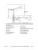
FIGURE C 28 54 45 66 54 50 3. 35 59 49 46 9 34 31 43 As you proceed with the assembly, installation, and adjustment steps in this manual you may find it helpful to refer back to this illustration of a completed installation. (See Figure C.
FIGURE D CHAIN (59) IDLER PULLEY (68) 4. TROLLEY (45) The Chain (59), Trolley (45), and Idler Pulley (68) have been pre-assembled in the Rail (35). Make sure these parts are complete and in good condition. (See Figure D.) FIGURE E RAIL BRACE (44) RAIL (35) 5. Lubricate the inside edges of the Rails (35) using grease. Place the Rails on a flat surface for assembly. All four Rails are interchangeable. Slide a Rail Brace (44) onto a Rail. Connect a Rail by sliding a Rail Brace onto the next Rail.
WASHER (38) ELASTIC SPACER (39) BRACKET (36) RAIL (35) HEX BOLT (37) FIGURE F IDLER PULLEY (68) SPROCKET (41) HOUSING (31) 6. Remove the four Hex Bolts (37), four Washers (38), and four Elastic Spacers (39) from the top of the Housing (31). Place the assembled Rail (35) on the Housing, flush with the stop on top of the Housing. Wrap the Chain (59) over the Housing’s Sprocket (41). Push the Idler Pulley (68) assembly toward the front of the Rail to eliminate excess slack in the Chain.
FIGURE H FLAT WASHER (64) SPRING (65) RAIL (35) RAIL (35) NUT (63) CARRIAGE BOLT (69) 8. Slide the Header Bracket (54) onto the Rail (35). Insert a Flat Washer (64) and Spring (65) onto the Carriage Bolt (69). Thread a Nut (63) onto the Carriage Bolt until it is finger tight. Use an open-end wrench (not included) to tighten the Nut until the Chain (59) is not against the inside surface of the Rail (35). (See Figure H.) 9. Disengage all existing garage door locks to avoid damage to the door.
12. Refer to the vertical and horizontal lines drawn in Figure I for proper placement of the Header Bracket (54). FIGURE J HEADER BRACKET (54) VERTICAL CENTER LINE HORIZONTAL LINE HEADER BRACKET (54) MOUNTING HOLES HEX TAPPING SCREW (55) 2” VERTICAL CENTER LINE HEX TAPPING SCREW (55) 6” CONCRETE ANCHOR (56) a. Wall Mount: Center the Header Bracket (54) on the vertical center line with the bottom edge of the Header Bracket on the horizontal line (with the arrow pointing toward the ceiling).
FIGURE K R-PIN (52) PIN (51) RAIL (35) PIN (51) R-PIN (52) PACKAGING MATERIAL 13. Position the Garage Door Opener on the garage floor below the unit’s previously installed Header Bracket (54). Use product packaging material to protect the Housing (31). Raise the Rail (35) until the two holes at the end of the Rail align with the two holes in the Header Bracket. Secure the Rail to the Header Bracket using a Pin (57). Insert an R-Pin (58) in the Pin to secure the Pin in place. (See Figure K.
tions. The Trolley can remain disconnected until connecting the Straight Door Arm (46) to the Trolley is completed. (See Figure L.) HANGING BRACKET (28) FIGURE M HANGING BRACKET (28) CONCRETE ANCHOR (30) CONCRETE ANCHOR (30) TAPPING SCREW (29) TAPPING SCREW (29) NUT (27) NUT (27) HEX BOLT (26) 30 26 27 29 15. Lift the garage door to its full open position, and rest the Garage Door Opener on the garage door.
FIGURE O R-PIN (52) DOOR BRACKET (50) PIN (51) NUT (48) WASHER (38) STRAIGHT DOOR ARM (46) CURVED DOOR ARM (49) R-PIN (52) HEX BOLT (47) R-PIN (52) WASHER (38) PIN (51) NUT (48) HEX BOLT (47) PIN (51) HEX BOLT (47) WASHER (38) NUT (48) R-PIN (52) PIN (51) 19. Fasten the Straight Door Arm (46) and Curved Door Arm (49) together to the longest possible length (with a 2 or 3 hole overlap) using two Hex Bolts (47) and two Nuts (48). (See Figure O, Illustration A.) 20.
FIGURE P TERMINAL #2 WIRES TERMINALS #1 & #2 DOOR CONTROL ASSEMBLY (74) WIRES WIRES TERMINAL #1 TAPPING SCREW (73) CONCRETE ANCHOR (56) TAPPING SCREWS (73) WIRES HOUSING (31) 24. Locate the Door Control (74) assembly where the garage door is visible, away from the garage door and out of reach of children. Mount the Door Control assembly at least 5 feet above the floor. (See Figure P.
ADJUSTMENT Setting Remote Control Codes: 1. The Garage Door Opener’s Receiver and Remote Controls (75) transmitter are set to a matching code. If you purchase additional Remote Controls, the Garage Door Opener must be programmed to accept the new Remote Control. FIGURE Q . A B (> 1 Second) 2X . C D 2. Plug the Power Cord (9) into the nearest 120 volt, grounded, electrical outlet. The Digital Display on the Housing (31) will flash with “H”, and the Light will illuminate. The unit is in standby.
Setting Opening Limit: 4 Seconds Figure R 7. Press and hold the “SET” Button for more than four seconds. The Digital Display will indicate “1”. Press and release the “SET” Button again and “1” will flash in the Digital Display. Now the unit will enter into a limit setting mode. (See Figures R and S.) Figure T 8. Figure S Figure U Press and hold the “UP” Button. The unit’s Motor will move the door towards the open position. The Digital Display will indicate “n” and the Motor will move the door upward.
Setting Closing Limit: Figure V 9. Figure W Press the “UP” Button and the Digital Display will indicate “2”. Press and release the “SET” Button. The Digital Display will indicate a flashing “2”. The unit is now ready for setting the close limit. (See Figures V and W.) Figure X Figure Y 10. Press the “DOWN” Button. The Motor will move the door towards the close position. The Digital Display will indicate a flashing “u”. The CLOSE position can be adjusted by pressing the “UP/DOWN” Button.
Setting Opening Force: Figure BB Figure CC 12. Press and hold the “SET” Button for more than four seconds. Repeatedly press the “UP” Button until the Digital Display indicates “3”. Press and release the “SET” Button. The Digital Display will indicate a flashing “3”. Now the unit will enter into a Force Adjustment mode. (See Figures BB and CC.) (1-9) Figure DD (9-1) Figure EE 13. Press and release the “UP” Button.
Setting Closing Force: Figure II Figure JJ 15. Press and hold the “SET” Button for more than four seconds. The Digital Display will indicate “1”. Repeatedly press the “UP” Button until the Digital Display indicates “4”. Press and release the “SET” Button. The Digital Display will indicate a flashing “4”. Now the unit enters into the close force mode. (See Figures II and JJ.) (1-9) Figure KK (9-1) Figure LL 16. Press and release the “UP” Button.
Setting Automatic Closing Time: Figure PP Figure QQ 18. Press and hold the “SET” Button for more than four seconds. Press the “UP” Button and choose figure “5”. Press and release the “SET” Button. The Digital Display will indicate a flashing “5”. Now the unit enters into the setting the automatic closing time mode. (See Figures PP and QQ.) (0-9) Figure RR (9-0) Figure SS 19. Press and release the “UP” Button.
the “SET” Button. The Digital Display will indicate “h”. Now the automatic closing time has been set. (See Figures TT and UU.) Setting Automatic Closing Time: Figure VV Figure WW 21. Press and hold the “SET” Button for more than four seconds. Press the “UP” Button and choose figure “6”. Press and release the “SET” Button. The Digital Display will indicate a flashing “6”. Now the unit enters into the setting the photocell detector mode. (See Figures VV and WW.) Figure XX 22.
To test the safety reverse system: 25. The safety reverse system test is important. The garage door must reverse on contact with a 1-1/2” thick obstacle laid flat on the garage floor. Failure to properly adjust the Garage Door Opener may result in serious personal injury from a closing garage door. Repeat this test once a month and adjust as needed. 26. Place a 1-1/2” thick obstacle flat on the floor under the garage door. Operate the door in the down direction. The door must reverse on the obstruction.
Maintenance And Servicing 3. REMOTE CONTROL: The alkaline Batteries (23AE12V) should produce power for up to three months. If the transmission range decreases, replace the Battery. To do so, use a screwdriver blade to pry open the Cover. Insert the new Battery positive side up. Then replace the Cover. Do not dispose of the old Battery with household waste. Take the Battery to a proper disposal center. 4. OPENER LIGHT: To replace the Opener Light open the Light Cover (34).
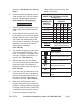
Problem Opener does not operate with Remote. Remote Control has short range. Troubleshooting Possible Causes Possible Solutions 1. No power at outlet. 1. Check power at outlet. 2. Power Cord not connected. 2. Check that Power Cord is plugged in. 3. Garage Door is locked. 3. Disengage all locks on Garage Door. 4. Excessive build-up of ice, snow, dirt, and/or debris under Garage Door. 4. Clean out from under Garage Door. 5. Garage Door is frozen to the ground. 5. Thaw out area under Garage Door.
PARTS LIST Part # Description Qty. Part # Description Qty. Record Product’s Serial Number Here: Note: If product has no serial number, record month and year of purchase instead. Note: Some parts are listed and shown for illustration purposes only, and are not available individually as replacement parts. SKU 65712 For technical questions, please call 1-800-444-3353.
ASSEMBLY DIAGRAM SKU 65712 For technical questions, please call 1-800-444-3353.
LIMITED 90 DAY WARRANTY Harbor Freight Tools Co. makes every effort to assure that its products meet high quality and durability standards, and warrants to the original purchaser that this product is free from defects in materials and workmanship for the period of 90 days from the date of purchase.