Table of Contents Safety ......................................................... 2 Maintenance .............................................. 12 Setup .......................................................... 6 Parts List and Diagram .............................. 14 Specifications ............................................. 6 Warranty .................................................... 16 SAFETY Operation ...................................................
IMPORTANT SAFETY INFORMATION WARNING Read all safety warnings and instructions. Failure to follow the warnings and instructions may result in electric shock, fire and/or serious injury. Save all warnings and instructions for future reference. The warnings, precautions, and instructions discussed in this instruction manual cannot cover all possible conditions and situations that may occur.
Air Compressor Safety Warnings SAFETY 1. Risk of fire or explosion - do not spray flammable liquid in a confined area or towards a hot surface. Spray area must be well-ventilated. Do not smoke while spraying or spray where spark or flame is present. Arcing parts - keep compressor at least 20 feet away from explosive vapors, such as when spraying with a spray gun. 2. Risk of bursting - do not adjust regulator higher than marked maximum pressure of attachment. 3.
TO PREVENT ELECTRIC SHOCK AND DEATH FROM INCORRECT GROUNDING WIRE CONNECTION: Check with a qualified electrician if you are in doubt as to whether the outlet is properly grounded. Do not modify the power cord plug provided with the compressor. Never remove the grounding prong from the plug. Do not use the compressor if the power cord or plug is damaged. If damaged, have it repaired by a service facility before use.
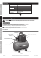
Specifications Electrical Rating 120VAC / 60Hz / 2.6A Air Outlet Size 1/ ″ 4 SAFETY Air Pressure Shut-off Restart Air Tank Capacity Air Flow Capacity Sound Level -18 NPT 100 PSI 85 PSI 3 Gallons 0.6 CFM @ 90 PSI 1.0 CFM @ 40 PSI 88 dB @ 1m 227847 Instructions for putting into use SETUP Read the ENTIRE IMPORTANT SAFETY INFORMATION section at the beginning of this manual including all text under subheadings therein before set up or use of this product.
1. Align the two mounting holes in the Handle with the two threaded mounting holes in the Bracket on the Air Tank. Secure the Handle to the Air Tank using the two Screws. 2. Break in the new Air Compressor as follows: 3. Connect a regulator valve, an inline shut off valve and a 1/4″ NPT air hose to the Quick Coupler (all sold separately). The air hose must be long enough to reach the work area with enough extra length to allow free movement while working.
For technical questions, please call 1-888-866-5797.
Item 69269 For technical questions, please call 1-888-866-5797.
Operating Instructions Read the ENTIRE IMPORTANT SAFETY INFORMATION section at the beginning of this manual including all text under subheadings therein before set up or use of this product. SAFETY Compressor Area Set Up 1. Designate a work area that is clean and well-lit. The work area must not allow access by children or pets to prevent injury. 2. Locate the Compressor on a flat level surface to ensure proper pump lubrication and to prevent damage to the unit.
Emergency Depressurization Automatic Shut off System 1. If the Compressor automatically shuts off before reaching its normal cutoff pressure: 2. Possible causes of repeated automatic shut off of the compressor are: a. Shut off all tools. a. Using an extension cord that is too long or narrow; b. Wait until the Compressor cools down (about 10 minutes); b. An air leak or open hose causing the compressor to cycle too often and build up heat. c.
Maintenance and Servicing Procedures not specifically explained in this manual must be performed only by a qualified technician. SAFETY TO PREVENT SERIOUS INJURY FROM ACCIDENTAL OPERATION: Turn the Power Switch “OFF” and unplug the Compressor from its electrical outlet before performing any inspection, maintenance, or cleaning procedures. TO PREVENT SERIOUS INJURY FROM COMPRESSOR FAILURE: Do not use damaged equipment. If abnormal noise or vibration occurs, have the problem corrected before further use.
Troubleshooting 1. 2. 3. 4. 5. Thermal overload switch tripped. 5. 6. Building power supply circuit tripped or blown fuse. 6. 7. Cord wire size is too small or cord is too 7. long to properly power compressor. Compressor builds pressure too slowly 8. Compressor needs service. 8. 1. Incorrect power supply. 2. Working environment too cold. 1. Check that circuit matches compressor requirements. 2. Move compressor to a warmer location. Check that recommended oil is in crankcase. 3.
Parts List and Diagram PLEASE READ THE FOLLOWING CAREFULLY SAFETY THE MANUFACTURER AND/OR DISTRIBUTOR HAS PROVIDED THE PARTS LIST AND ASSEMBLY DIAGRAM IN THIS MANUAL AS A REFERENCE TOOL ONLY. NEITHER THE MANUFACTURER OR DISTRIBUTOR MAKES ANY REPRESENTATION OR WARRANTY OF ANY KIND TO THE BUYER THAT HE OR SHE IS QUALIFIED TO MAKE ANY REPAIRS TO THE PRODUCT, OR THAT HE OR SHE IS QUALIFIED TO REPLACE ANY PARTS OF THE PRODUCT.
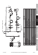
Assembly Diagram 3 6 4 3 1 6 1 8 5 2 6 2 5 7 4 8 5 8 3 1 1 4 1 4 3 1 1 7 1 0 8 1 5 3 2 1 2 3 2 7 2 0 1 7 1 9 7 0 1 3 1 1 6 5 1 3 SETUP 6 1 SAFETY 4 9 4 4 4 5 4 2 2 9 2 6 9 3 4 2 4 2 0 4 0 3 9 2 7 2 5 2 8 4 2 4 1 5 0 3 7 3 8 3 3 5 6 5 1 OPERATION 3 0 2 3 4 7 3 5 5 3 5 4 5 5 5 9 Item 69269 MAINTENANCE 4 6 6 0 For technical questions, please call 1-888-866-5797.
Limited 90 Day Warranty Harbor Freight Tools Co. makes every effort to assure that its products meet high quality and durability standards, and warrants to the original purchaser that this product is free from defects in materials and workmanship for the period of 90 days from the date of purchase.
Garantía limitada de 90 días Harbor Freight Tools Co. hace todo lo posible para asegurar que sus productos cumplen con altos estándares de calidad y durabilidad, y garantiza al comprador original que este producto está libre de defectos en sus materiales y mano de obra durante un plazo de 90 días a partir de la fecha de compra.
Diagrama de montaje 36 61 57 48 58 31 14 52 62 14 31 32 15 32 12 7 20 17 19 49 44 45 43 16 18 17 13 11 10 8 6 5 1 3 2 4 70 29 SEGURIDAD CONFIGURACIóN 30 26 24 34 20 40 39 27 25 28 9 42 41 50 56 38 33 37 51 23 FUNCIONAMIENTO 46 47 35 53 MANTENIMIENTO 54 55 59 60 Si desea realizar preguntas técnicas, llame al 1-888-866-5797.
Lista de piezas y diagrama POR FAVOR, LEA ESTO CON DETENIMIENTO SEGURIDAD EL FABRICANTE Y/O DISTRIBUIDOR HA PROPORCIONADO LA LISTA DE PIEZAS Y EL DIAGRAMA DE MONTAJE QUE SE MUESTRAN EN ESTE MANUAL ÚNICAMENTE COMO HERRAMIENTA DE REFERENCIA. NI EL FABRICANTE NI EL DISTRIBUIDOR ASEVERAN O GARANTIZAN DE NINGÚN MODO QUE EL/LA COMPRADOR(A) ESTÉ CALIFICADO(A) PARA REALIZAR REPARACIONES AL PRODUCTO, NI QUE ÉL/ELLA ESTÉ CALIFICADO(A) PARA REEMPLAZAR NINGUNA PIEZA DEL PRODUCTO.
Resolución de problemas Problema El compresor no arranca o no vuelve a arrancar Causas posibles 1. El/los tanque(s) ya están presurizados. 2. El cable de suministro eléctrico no está correctamente enchufado. 3. Fuente de alimentación incorrecta. 4. No hay energía en el tomacorriente. 5. Se disparó el interruptor de sobrecarga térmica. 6. El circuito eléctrico del edificio se disparó o se quemó un fusible. 7.
Mantenimiento y servicio técnico SEGURIDAD Un técnico calificado debe realizar los procedimientos que no se expliquen específicamente en este manual. ADVERTENCIA PARA EVITAR LESIONES GRAVES CONSECUENCIA DE UN FUNCIONAMIENTO ACCIDENTAL: Antes de realizar cualquier tarea de inspección, mantenimiento o limpieza, coloque el interruptor de alimentación en la posición "OFF" (APAGADO) y desenchufe el compresor del tomacorriente.
12. Cierre la válvula de cierre en línea. 13. Purgue el aire de la herramienta; luego, desconéctela. 14. Gire dos vueltas la válvula de drenaje, ubicada en la base del tanque, para liberar cualquier humedad acumulada y la presión interna del tanque. Cuando la humedad haya drenado, cierre la válvula. No extraiga la válvula de drenaje. 15. Limpie el compresor de aire; luego, guárdelo bajo techo.
Instrucciones para la operación SEGURIDAD Antes de instalar o usar este producto, lea la TOTALIDAD de la sección "INFORMACIóN IMPORTANTE SOBRE SEGURIDAD" que se encuentra al comienzo de este manual, incluyendo todos los textos debajo de los subtítulos. Preparación del área de ubicación del compresor 1. Elija un área de trabajo que esté limpia y bien iluminada. El área de trabajo debe estar fuera del alcance de los niños y mascotas, para evitar lesiones. 3.
A B C D E F G H I Página 9 Si desea realizar preguntas técnicas, llame al 1-888-866-5797.
SEGURIDAD CONFIGURACIóN FUNCIONAMIENTO MANTENIMIENTO Artículo 69269 Conecta el aire a la herramienta Evita que la suciedad y la condensación causen daños a la herramienta o pieza de trabajo Regula la presión de aire a la herramienta Para la lubricación de herramientas neumáticas Proporciona una conexión y liberación rápidas Aumenta la vida útil del acoplador Evita que el vapor de agua dañe la pieza de trabajo Para el ajuste fino del flujo de aire en la herramienta Función Figura B: Configuración del s
Montaje/ensamblaje 1. Alinee los dos orificios de montaje de la manija con los dos orificios de montaje con rosca del soporte del tanque de aire. Fije la manija al tanque de aire con dos tornillos. 2. Para asentar su nuevo compresor de aire, siga estos pasos: a. Apague el interruptor de alimentación y desenchufe la unidad. Inserte un acoplador macho (se vende por separado) en el acoplador rápido hembra y abra por completo todos los reguladores y todas las válvulas. b.
Especificaciones SEGURIDAD 1/ ″ 4 Tamaño de la salida de aire 120 VAC / 60 Hz / 2,6 A Valor eléctrico nominal Presión de aire Apagado Rearranque -18 NPT 100 PSI 85 PSI Capacidad del tanque de aire 3 galones Capacidad de flujo de aire Nivel de ruido 0,6 CFM a 90 PSI 1,0 CFM a 40 PSI 88 dB a 1m 227847 CONFIGURACIóN Instrucciones para la puesta en uso Antes de instalar o usar este producto, lea la TOTALIDAD de la sección "INFORMACIóN IMPORTANTE SOBRE SEGURIDAD" que se encuentra al comienzo de este
Conexión a tierra ADVERTENCIA PARA EVITAR DESCARGAS ELÉCTRICAS Y LA MUERTE POR CAUSA DE UNA CONEXIóN A TIERRA INCORRECTA DE LOS CABLES: Consulte a un electricista calificado si tiene dudas acerca de la correcta conexión a tierra del tomacorriente. No modifique el enchufe del cable de suministro eléctrico que se proporciona con el compresor. Nunca quite la pata de puesta a tierra del enchufe. No utilice el compresor si el cable de suministro eléctrico o el enchufe están dañados.
Advertencias de seguridad del compresor de aire SEGURIDAD 1. Riesgo de incendio o explosión - no pulverice líquido inflamable en un área cerrada o en dirección a una superficie caliente. El área de pulverización debe estar bien ventilada. No fume mientras realiza la pulverización, ni pulverice en presencia de chispas o llama. Piezas que forman arcos eléctricos - mantenga el compresor al menos a 20 pies de distancia de vapores explosivos, como por ejemplo cuando se utilizan pistolas pulverizadoras. 2.
INFORMACIóN IMPORTANTE SOBRE SEGURIDAD Advertencias de seguridad generales ADVERTENCIA Lea todas las advertencias e instrucciones de seguridad. No seguir las advertencias e instrucciones puede ocasionar descarga eléctrica, incendio y/o lesiones graves. Conserve todas las advertencias e instrucciones para referencia futura. Las advertencias, precauciones e instrucciones que se ofrecen en este manual de instrucciones no pueden cubrir todas las situaciones y condiciones posibles que pueden ocurrir.
Contenido SEGURIDAD Garantía..................................................... 16 Especificaciones ......................................... 6 Lista de piezas y diagrama ........................ 14 Configuración ............................................. 6 Mantenimiento ........................................... 12 Seguridad ................................................... 2 Funcionamiento .........................................