7" PORTABLE WET CUTTING TILE SAW Model 40315 SET UP AND OPERATING INSTRUCTIONS Please Note: Diamond Blade not included, sold separately. Visit our website at: http://www.harborfreight.com Read this material before using this product. Failure to do so can result in serious injury. SAVE THIS MANUAL. Copyright© 2008 by Harbor Freight Tools®. All rights reserved.
NOTICE is used to address practices not related to personal injury. SAVE THIS MANUAL Keep this manual for the safety warnings and precautions, assembly, operating, inspection, maintenance and cleaning procedures. Write the product’s serial number in the back of the manual near the assembly diagram (or month and year of purchase if product has no number). Keep this manual and the receipt in a safe and dry place for future reference.
plugs with grounded power tools. Unmodified plugs and matching outlets will reduce risk of electric shock. tion. Safety equipment such as dust mask, non-skid safety shoes, hard hat, or hearing protection used for appropriate conditions will reduce personal injuries. b. Avoid body contact with grounded surfaces such as pipes, radiators, ranges and refrigerators. There is an increased risk of electric shock if your body is grounded. c. Keep guards in place and in good working order. d.
do the job better and safer at the rate for which it was designed. b. Do not use the power tool if the switch does not turn it on and off. Any power tool that cannot be controlled with the switch is dangerous and must be repaired. ent from those intended could result in a hazardous situation. 5. a. Have your power tool serviced by a qualified repair person using only identical replacement parts. This will ensure that the safety of the power tool is maintained. c.
4. Use tools with the lowest vibration when there is a choice between different processes. 5. Include vibration-free periods each day of work. 6. Grip tool as lightly as possible (while still keeping safe control of it). Let the tool do the work. 7. To reduce vibration, maintain the tool as explained in this manual. If any abnormal vibration occurs, stop use immediately. SPECIFIC SAFETY WARNINGS 1. 2. 3. Maintain labels and nameplates on the Tile Saw. These carry important information.
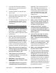
POWER CORD TILE SAW 120 VOLT, GROUNDED ELECTRICAL OUTLET DRIP LOOP Figure 1 14. Always arrange a “drip loop” in the Power Cord/Plug (34) connecting the Tile Saw to a 120 volt, grounded, electrical outlet. A drip loop is that part of the Power Cord below the level of the outlet, or the connector if an extension cord is used, to prevent water traveling along the Power Cord and coming in contact with the outlet. If the Power Plug or electrical outlet does get wet, do not unplug the Power Cord.
27. Never attempt to remove material stuck in the moving parts of the Tile Saw while it is plugged in and running. 28. When cutting a large work piece make sure its entire length is properly supported. If necessary, use a roller stand (not included) with larger work pieces. 29. Never lean on the Tile Saw. Serious injury could result if the Tile Saw is tipped or if the rotating Saw Blade is accidently contacted. 30. Industrial applications must follow OSHA requirements. 31.
situations that may occur. It must be understood by the operator that common sense and caution are factors which cannot be built into this product, but must be supplied by the operator. 6. Do not use accessories which are not specifically designed and recommended by the tool manufacturer. Just because the accessory can be attached to your power tool, it does not assure safe operation. 7. The rated speed of the accessory must be at least equal to the maximum speed marked on the power tool.
cause injury beyond immediate area of operation. 11. Position the cord clear of the spinning blade. If you lose control, the cord may be cut or snagged and your hand or arm may be pulled into the spinning accessory. Avoid unintentional starting. Prepare to begin work before turning on the tool. 12. Do not leave the tool unattended when it is plugged into an electrical outlet. Turn off the tool, and unplug it from its electrical outlet before leaving. 13. This product is not a toy.
low resistance path to carry electricity away from the user, reducing the risk of electric shock. (See 3-Prong Plug and Outlet.) GROUNDING TO PREVENT ELECTRIC SHOCK AND DEATH FROM INCORRECT GROUNDING WIRE CONNECTION: Check with a qualified electrician if you are in doubt as to whether the outlet is properly grounded. Do not modify the power cord plug provided with the tool. Never remove the grounding prong from the plug. Do not use the tool if the power cord or plug is damaged.
3. 4. 5. 6. As the distance from the supply outlet increases, you must use a heavier gauge extension cord. Using extension cords with inadequately sized wire causes a serious drop in voltage, resulting in loss of power and possible tool damage. (See Table A.) The smaller the gauge number of the wire, the greater the capacity of the cord. For example, a 14 gauge cord can carry a higher current than a 16 gauge cord. (See Table A.
SPECIFICATIONS Blade Diameter (Blade Not Included, Sold Separately) 7" (67393 7” Continuous Rim Diamond Blade Recommended) Arbor Diameter 1" Maximum Cutting Capacity 1” Thick, 12” Wide Electrical Requirements 120 V~ / 60 Hz / 5 A Single Phase Tilting Head 45° for Bevels Blade Rated Speed 3565 RPM Table Size 15-3/4” x 16-1/2” Accessories 1 Spanner Wrench 1 Nut Driver Note: For additional information regarding the parts listed in the following pages, refer to the Assembly Diagram near the end
ing sure no hidden electric cords or cables are in the drilling path. 6. Once the mounting holes are drilled, align the four 7/16” wide x 3-1/2” long mounting slots in the base of the Inner Cover (16) with the four predrilled mounting holes in the workbench. Secure the Tile Saw to the workbench, using four appropriate length Bolts, Lock Washers, and Nuts (not included). To Attach The Star Knob: 1. 2. The Star Knob (53) is used to lock the Cutting Guide (57) in position.
OPERATING INSTRUCTIONS 5. Read the ENTIRE IMPORTANT SAFETY INFORMATION section at the beginning of this manual including all text under subheadings therein before set up or use of this product. Store idle tools out of reach of children and other untrained persons. Tools are dangerous in the hands of untrained users. 6. Maintain tools with care. Keep tools clean. Properly maintained tools are easier to control. Do not use a damaged tool. Tag damaged tools “Do not use” until repaired. 7.
off Tile Saw. Unplug machine, and refill Tray to appropriate level. Restart Tile Saw. General Operating Instructions 1. Fill Tray (17) with water and carefully slide Tray under Blade. Make sure water level is deep enough to cover lower edge of Cutting Wheel Blade, but not so deep as to spill over edge of Tray. (See Figure 3, below.) 2. Loosen Star Knob (20) and adjust the Cutting Guide (57) to set desired cutting width. Retighten the Star Knob. 3.
MAINTENANCE AND SERVICING Procedures not specifically explained in this manual must be performed only by a qualified technician. TO PREVENT SERIOUS INJURY FROM ACCIDENTAL OPERATION: Turn the Power Switch of the tool to its “OFF” position and unplug the tool from its electrical outlet before performing any inspection, maintenance, or cleaning procedures. TO PREVENT SERIOUS INJURY FROM TOOL FAILURE: Do not use damaged equipment.
(not included, sold separately), making sure to install Blade according to indicated rotation direction on Blade. F. Replace the Outside Flange (7) and Nut (4). Use the Spanner (59) to hold the Outside Flange (7) while you tighten the Nut (4) securely with the Nut Driver (60). Do not overtighten. G. Replace the Front Cover (1), Rear Blade Cover (58), Screws (2), Washers (3), and Tray (17) in the reverse order of removal. 8. To clean: Wipe with a damp cloth, vacuum or use compressed air.
PARTS LIST Part Description Part Description Part Description 1 Front Cover 21 Power Switch 41 Motor Lead Wire 2 Screw (M4x10) 22 Switch Seal 42 Motor 3 Washer (M4) 23 Switch Cover 43 Rear Cover 4 Nut (M12) 24 Inlet Clip 44 Handle 5 Lock Washer (M12) 25 Rubber Collar 45 Washer (M6) 6 Washer (M12) 26 Washer (M4) 46 Bolt (M6x10) 7 Outside Flange 27 Screw (M4x10) 47 Holder 28 Copper Nut (M4) 48 Square Cap 9 Inner Flange 29 Lock Washer (M4) 49 Blade Guard
ASSEMBLY DIAGRAM 18 Record Product’s Serial Number Here: Note: If product has no serial number, record month and year of purchase instead. Note: Some parts are listed and shown for illustration purposes only, and are not available individually as replacement parts. SKU 40315 For technical questions, please call 1-800-444-3353.
90 Day Warranty Harbor Freight Tools Co. makes every effort to assure that its products meet high quality and durability standards, and warrants to the original purchaser that this product is free from defects in materials and workmanship for the period of 90 days from the date of purchase.