INSTALLATION INSTRUCTIONS INSTRUCCIONES DE INSTALACIÓN Automated Flat Panel Ceiling Lift Elevador automatizado de techo para televisor de pantalla plana This device complies with part 15 of the FCC rules. Operation is subject to the following 2 conditions: (1) This device may not cause harmful interference, and (2) this device must accept any interference received, including interference that may cause undesired operation.
CM2C40 Installation Instructions Milestone AV Technologies, and its affiliated corporations and subsidiaries (collectively, "Milestone"), intend to make this manual accurate and complete. However, Milestone makes no claim that the information contained herein covers all details, conditions or variations, nor does it provide for every possible contingency in connection with the installation or use of this product.
Installation Instructions CM2C40 CONTENTS INSTALLATION REQUIREMENTS .............................................................................................................. 6 Power Requirements and Wiring ................................................................................................................ 6 INSTALLATION ............................................................................................................................................
CM2C40 Installation Instructions DIMENSIONS CEILING MOUNTING HOLES .406 TOP MOUNTING BUTTON HEIGHT MIN 7.10 MAX 13.60 19.00 28.38 7.75 MIN HEIGHT 31.25 .13 (2) SIDE MOUNTING BRACKETS (1 PER SIDE) 1.31 2.50 19.25 1.67 DOOR BRACKET AND MOUNTING HOLES 7.00 3.26 23.75 21.75 4.00 NOTES: 1. THE CUSTOM INTERFACE BRACKET REQUIRED FOR YOUR FLAT PANEL (NOT SHOWN) WILL ADD BETWEEN 1/2" AND 2" IN DEPTH AND MAY AFFECT THE LOCATION OF THE FLAT PANEL ON THE MOUNT. 2. ALLOW FOR A MINIMUM OF 1.
Installation Instructions CM2C40 LEGEND Tighten Fastener Pencil Mark Apretar elemento de fijación Marcar con lápiz Loosen Fastener Drill Hole Aflojar elemento de fijación Perforar Phillips Screwdriver Adjust Destornillador Phillips Ajustar Open-Ended Wrench Remove Llave de boca Quitar By Hand Optional A mano Opcional Hex-Head Wrench Security Wrench Llave de cabeza hexagonal Llave de seguridad 5
CM2C40 Installation Instructions INSTALLATION REQUIREMENTS 1. The CM2C40 has been designed to be mounted either hanging from an overhead structure or mounted to existing stud wall structures. 2. 3. Install interface bracket or mounting buttons to display following the instructions provided with bracket. Measure the distance from the center of an upper mounting button to the highest point of the display. Record measurement.
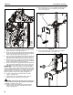
Installation Instructions CM2C40 6 10 10 6 x2 9 Figure 5 5 4 Figure 3 7. 8. Remove two locknuts securing faceplate to faceplate mounting bracket. (See figure 4) Move faceplate up one set of holes to adjust location 1" or two sets of holes to adjust 2". (See figure 4) 1" (25MM) 10. Using the remote control, lower the lift until it stops. (See figure 3) If more than 2" of faceplate adjustment is required: 11. Raise lift following instructions in step 6. (See figure 3) 12.
CM2C40 Installation Instructions 15. Align studs in faceplate with appropriate holes in faceplate mounting bracket and hang faceplate on bracket with studs. 16. Secure faceplate to faceplate mounting bracket using two locknuts. (See figure 7) 3. 4. 5. Slide cable guide side cover away from mount and carefully set aside. Loosen three cable clamps. (See figure 10) Route cable(s) down through upper cable clamp.
Installation Instructions CM2C40 5 From Display 4 x1 13 Upper cable clamp Do NOT use cable ties within area inside dotted line! 6 Lower cable clamps 12 4 x2 14 Figure 10 9
CM2C40 Installation Instructions 15. Slide cable guide side cover over CM2 mount lining up two holes in cable guide side cover with two holes in CM2 mount. (See figure 12) 6 Cable guide side cover 10 11 8 9 8 7 15 9 Cable pulley center shaft Figure 11 7. Route cables under cable pulley and up over top of cable pulley. (See figure 10) and (See figure 11) 8. Route one cable from front (black) cable clamps through the #2 cable opening and straight down next to the cable pulley center shaft.
Installation Instructions CM2C40 of travel must be considered when location the mount and a stop bar must be installed along the top edge of the opening in the ceiling. The stop bar must span the entire width of the front and back openings, and protrude outward into the opening a minimum of 1/2".
CM2C40 Installation Instructions 7. While maintaining dimensions referenced in figure 15, mark base plate mounting hole locations. (See figure 16) 8. Drill pilot holes at marked locations. 9. Mark four side bracket mounting hole locations if applicable. (See figure 16) 10. Drill four pilot holes at marked locations. 11. Secure base plate to structure using either two (wall mount) or six (ceiling mount) 5/16" flat washers and two or six six 5/16" x 2 1/2" lag screws. (See figure 16) 12.
Installation Instructions CM2C40 NOTE: Holes are provided in the faceplate for use with a padlock or similar locking device, if desired. In addition, the pin and nut may be removed from the upper holes and moved to the lower holes for use as a more permanent locking device.
CM2C40 Installation Instructions 2. Bottom Cover Installation If the dimension identified during step 1 above is equal to or less than the thickness of the bottom cover being installed, the display travel limits must be adjusted before continuing to avoid a collision scenario between the bottom cover and the ceiling. Refer to step 6 below.
Installation Instructions 5. CM2C40 Assemble bottom cover to cover mounting plate using #10-24 screws a minimum of 1/4" plus the thickness of the cover material long. (not provided). (See figure 25) There is an upward travel limit adjustment screw and a downward travel limit adjustment screw located on the top right hand side of the mount. (See figure 27) NOTE: 10 full turns of the "Extend" or "Retract" travel adjustment screws is equal to 1" of display travel. Cover Mounting Plate Bottom Cover 6. 7.
CM2C40 Installation Instructions Lift Column Bearing Adjustment The upper and lower lift columns are aligned using two lift bearings, one upper and one lower. Bearing adjustment is pre-set at the factory, however, there may be times when it is required to make slight adjustments in bearing tightness to eliminate excess play in lift columns or noise.
Installation Instructions Extended Programming Capabilities CM2C40 Normal Operating Mode The CM2C40 allows for extended programming to make the mount compatible with other devices such as a Universal Remote or other control devices through a serial connection. 1 2 3 Setting or changing the configuration of the CM2C40 is done through the remote control provided with the mount.
CM2C40 Installation Instructions IR-SE15 Programming IR-SE15 Control Features: • • • 1 Carrier Frequency:38KHz Protocol:NEC - Full Repeat System Code(s):6E (Default) - Multiple Codes Selected via Key-Press (see below) 2 3 4 6 Table 1: IR-SE15 Control Codes KEY FUNCTION HEX CODE 1 NOT USED N/A 2 NOT USED N/A 3 EXTEND DISPLAY 07 4 NOT USED N/A 5 STOP 0A 6 NOT USED N/A 7 RETRACT DISPLAY 0D 8 NOT USED N/A 9 NOT USED N/A 10 NOT USED N/A 11 NOT USED N/A 12 NOT USED N/A
Installation Instructions CM2C40 Serial Communications Address Description NOTE: Check with the appropriate automation system vendor Multiple Chief devices can be used on the same network by setting each device to a different address. for available drivers and/or software for any external devices. Notes: NOTE: All units ship with a default address of 00. NOTE: Broadcast messages will command all devices on the [PR] = Product ID (CM2C40 = 02) same network.
CM2C40 Installation Instructions 1st Position of switch array 1st Position of connector array 1st Position of connector array Figure 30 CM2C40 Interface Board Hardware Information (See figure 30) Dry Contact Closures The unit provides dry contact outputs for system feedback, or to control other devices. To complete circuits to external devices: 1. 2. 3. Connect the common wire from your switch to terminal 7. (See figure 31) Connect the 'up' wire from your switch to terminal 5.
Installation Instructions CM2C40 J1 Pin 1 Isolated Extend/Retract Input (+) Pin 2 Isolated Extend/Retract Input (-) Pin 3 Isolated Voltage Sense Input (+) Pin 4 Isolated Voltage Sense Input (-) Pin 5 24V DC Supply Out (150ma Max.) Pin 6 Ground Pin 7 RS485 Ref.
CM2C40 Installation Instructions Voltage Sense External Power Source Unit extends and stays extended when voltage from an external source is applied across pins 3 and 4 on connector J1. When voltage is removed unit retracts. (See figure 30) and (See figure 33) Figure 33 Voltage Sense Internal 24V DC Power Source The 24V DC power supply that is built into the unit can be used to power external devices by using pins 5 and 6 on connector J1.
Installation Instructions CM2C40 Extend Limit Option Internal set of dry contacts close when unit is fully extended. Contact Rating: 30V AC or DC 1A max. (See figure 30) and (See figure 37) Figure 37 Retract Limit Option Internal set of dry contacts close when unit is fully retracted. Contact Rating: 30V AC or DC 1A max. (See figure 30) and (See figure 38) Figure 38 NOTE: Multiple control features can be used at the same time with the exception of the "Voltage Sense" feature.
CM2C40 Installation Instructions SW1 Switch 1 IR Switch 2 IR Switch 3 IR Switch 4 Not Used Switch 5 Not Used Switch 6 485 Address Switch 7 485 Address Switch 8 485 Address IR System Code Select Logic Switch Settings (Sw 1-3) Select 2 Select 1 Select 0 IR System Code OFF OFF OFF 6E OFF OFF ON E1 OFF ON OFF E2 OFF ON ON E3 ON OFF OFF E4 ON OFF ON E5 ON ON OFF E6 ON ON ON E7 RS485 Address Select Logic Switch Settings (Sw 6-8) Select 2 Select 1 Select 0 R
INSTRUCCIONES DE INSTALACIÓN Elevador automatizado de techo para televisor de pantalla plana Este dispositivo cumple con la Sección 15 de las normas de la Comisión Federal de Comunicaciones (FCC, por sus siglas en inglés) de los Estados Unidos. Su operación se encuentra sujeta a las dos condiciones siguientes: (1) este dispositivo no debe causar interferencias nocivas y (2) debe aceptar toda interferencia recibida, incluida aquella que pudiera provocar efectos indeseados en la operación.
CM2C40 Instrucciones de instalación Milestone AV Technologies y sus filiales y compañías asociadas (conjuntamente, "Milestone") procuran que este manual sea preciso y esté completo. No obstante, Milestone no garantiza que la información aquí incluida proporcione todos los detalles, las condiciones o las variaciones existentes, ni contemple todas las posibles contingencias relacionadas con la instalación o el uso de este producto.
Instrucciones de instalación CM2C40 ÍNDICE REQUISITOS DE INSTALACIÓN .................................................................................................................30 Requisitos de alimentación y cableado ..................................................................................................... 30 INSTALACIÓN .............................................................................................................................................
CM2C40 Instrucciones de instalación REFERENCIAS 28 Tighten Fastener Pencil Mark Apretar elemento de fijación Marcar con lápiz Loosen Fastener Drill Hole Aflojar elemento de fijación Perforar Phillips Screwdriver Adjust Destornillador Phillips Ajustar Open-Ended Wrench Remove Llave de boca Quitar By Hand Optional A mano Opcional Hex-Head Wrench Security Wrench Llave de cabeza hexagonal Llave de seguridad
Instrucciones de instalación CM2C40 CEILING MOUNTING HOLES .406 TOP MOUNTING BUTTON HEIGHT MIN 7.10 MAX 13.60 19.00 28.38 7.75 MIN HEIGHT 31.25 .13 (2) SIDE MOUNTING BRACKETS (1 PER SIDE) 1.31 2.50 19.25 DOOR BRACKET AND MOUNTING HOLES 1.67 7.00 3.26 23.75 21.75 4.00 NOTES: 1. THE CUSTOM INTERFACE BRACKET REQUIRED FOR YOUR FLAT PANEL (NOT SHOWN) WILL ADD BETWEEN 1/2" AND 2" IN DEPTH AND MAY AFFECT THE LOCATION OF THE FLAT PANEL ON THE MOUNT. 2. ALLOW FOR A MINIMUM OF 1.
CM2C40 Instrucciones de instalación REQUISITOS DE INSTALACIÓN 1. El CM2C40 ha sido diseñado para ser colgado de una estructura en altura o para ser montado en paredes existentes con estructura de montantes. 2. 3. Instale la placa de conexión o pernos de montaje al televisor siguiendo las instrucciones provistas con la placa. Mida la distancia que hay desde el centro de un perno de montaje superior hasta el punto más alto del televisor. Anote la medida.
Instrucciones de instalación CM2C40 6 10 10 6 9 x2 Figura 5 4 5 Figura 3 7. 8. Quite las dos tuercas de seguridad que sujetan la placa frontal a su soporte de sujeción. (Consulte la Figura 4). Suba la placa frontal un orificio para ajustar la posición 25,4 mm (1 pulgada) o dos orificios para ajustar la posición 50,8 mm (2 pulgadas). (Consulte la Figura 4). 25 mm (1") 8 10. Con el control remoto, baje el elevador hasta que se detenga. (Consulte la Figura 3).
CM2C40 Instrucciones de instalación 1 x2 12 x4 14 x4 13 Figura 6 15. Alinee los pernos roscados de la placa frontal con los orificios correspondientes del soporte de sujeción de dicha placa y cuelgue la placa frontal en el soporte mediante los pernos. 16. Fije la placa frontal a su soporte de sujeción con dos tuercas de seguridad. (Consulte la Figura 7). Cubierta lateral de la guía de cables Figura 8 3. Deslizándola, extraiga la cubierta lateral y apártela con cuidado.
Instrucciones de instalación CM2C40 4 Proveniente del televisor x1 5 5 6 8 4 x3 8 4 x2 7 7 9 9 10 10 Figura 10 33
CM2C40 Instrucciones de instalación 6. Pase los cables por la abertura ubicada en la parte posterior del soporte de sujeción, que constituye el sujetador de cable medio. (Consulte la Figura 10 y la Figura 11). NOTA: Si el enchufe de los cables no pasa por la abertura, afloje o quite uno de los tornillos que fijan el soporte de sujeción al marco y gire el soporte de sujeción que constituye el sujetador de cable medio hacia el costado, hasta que puedan pasarse los enchufes. 13.
Instrucciones de instalación CM2C40 Instalación del soporte El CM2C40 ha sido diseñado para ser colgado de una estructura en altura o para ser montado en paredes existentes con estructura de montantes. Las siguientes instrucciones suponen que se cuenta con una estructura y una superficie de montaje adecuadas y que los cables de alimentación y de señal han sido correctamente instalados. IMPORTANTE: El patrón de montaje del CM2C40 tiene un ancho de 483 mm (19 pulgadas).
CM2C40 Instrucciones de instalación 7. Manteniendo las distancias detalladas en la Figura 15, marque la ubicación de los orificios de montaje de la placa de apoyo. (Consulte la Figura 16). 8. Realice los orificios según las marcas. 9. Marque la ubicación de los cuatro orificios de montaje de las placas de sujeción laterales, si corresponde. (Consulte la Figura 16). 10. Realice los cuatro orificios según las marcas. 11.
Instrucciones de instalación CM2C40 NOTA: La placa frontal cuenta con orificios para utilizar un candado o un dispositivo de bloqueo similar si el usuario lo desea. Asimismo, la varilla y las tuercas pueden pasarse de los orificios superiores a los inferiores a fin de utilizarlos como dispositivo de bloqueo más permanente. (Consulte la Figura 19). ADVERTENCIA: SI NO SE INSTALA CORRECTAMENTE, EL ELEVADOR PUEDE CAUSAR LESIONES GRAVES O DAÑOS AL EQUIPO.
CM2C40 Instrucciones de instalación 2. Instalación de la cubierta inferior Si la medida tomada en el paso 1 es igual o inferior al espesor de la cubierta inferior que instalará, antes de continuar deberá ajustar los límites de desplazamiento del televisor a fin de evitar que la cubierta inferior choque con el techo. Consulte el paso 6 en la siguiente página.
Instrucciones de instalación 5. CM2C40 Fije la cubierta inferior a la placa de montaje de la cubierta utilizando tornillos n.º 10-24 de un largo mínimo de 6,35 mm (1/4") más el espesor de la cubierta (no incluidos). (Consulte la Figura 25). Placa de montaje de la cubierta inferior Cubierta inferior tornillo n.º 10-24 En el lateral superior derecho del soporte, hay un tornillo para ajustar el límite de desplazamiento ascendente y un tornillo para ajustar el límite de desplazamiento descendiente.
CM2C40 Instrucciones de instalación Ajuste de los cojinetes de las columnas de elevación Las columnas de elevación superior e inferior están alineadas mediante dos cojinetes de elevación, uno superior y otro inferior. El ajuste de los cojinetes viene configurado de fábrica. No obstante, a veces es necesario hacer pequeños ajustes en la tensión de los cojinetes a fin de eliminar el juego excesivo de las columnas o bien algún ruido. ADVERTENCIA: LA TENSIÓN EXCESIVA PUEDE DAÑAR EL EQUIPO.
Instrucciones de instalación Funciones de programación avanzadas CM2C40 Modo de operación normal El CM2C40 cuenta con funciones de programación avanzadas para compatibilizar el soporte con otros equipos, tales como un control remoto universal u otros dispositivos de control, a través de una conexión en serie. Para configurar el CM2C40, se utiliza el control remoto provisto con el soporte.
CM2C40 Instrucciones de instalación Programación del control remoto SE15 Funciones de control del SE15: • Frecuencia portadora: 38 kHz • Protocolo: NEC. Repetición completa. • Código(s) del sistema: 6E (predeterminado). Selección de otros códigos mediante los botones (ver a continuación).
Instrucciones de instalación CM2C40 Comunicaciones en serie Descripción de dirección: Es posible utilizar varios dispositivos Chief en una misma red si se asigna a cada uno de ellos una dirección distinta. NOTA: Todas las unidades se despachan con la dirección predeterminada en 00. NOTA: Consulte a un distribuidor de sistemas de automatización respecto de software o controladores disponibles para los dispositivos externos.
CM2C40 Instrucciones de instalación 1.a posición del conjunto de interruptores 1.a posición del conjunto de conectores 1.a posición del conjunto de conectores Figura 30 Información sobre la placa de interfaz del CM2C40 (Consulte la Figura 30). Cierres de contactos secos La unidad cuenta con salidas de contactos secos para retroalimentación del sistema o para control de otros dispositivos. Para conectar dispositivos externos: 1. Conecte el cable COMMON de su interruptor al terminal 7.
Instrucciones de instalación CM2C40 J1 Pin 1 Entrada de descenso/ascenso aislada (+) Pin 2 Entrada de descenso/ascenso aislada (-) Pin 3 Entrada de detección de voltaje aislada (+) Pin 4 Entrada de detección de voltaje aislada (-) Pin 5 Salida de suministro de 24 V CC (150 mA máximo) Pin 6 Conexión a tierra Pin 7 RS485 Ref.
CM2C40 Instrucciones de instalación Detección de voltaje: fuente de alimentación externa La unidad desciende y permanece en esa posición cuando se aplica voltaje de una fuente externa a través de los pines 3 y 4 del conector J1. Cuando se retira el voltaje, la unidad asciende. (Consulte la Figura 30 y la Figura 33).
Instrucciones de instalación CM2C40 Opción de límite de extensión El conjunto de contactos secos internos se cierra cuando la unidad alcanza el límite de extensión. Régimen de trabajo del contacto: 30 V CA o CC 1 A máximo (Consulte la Figura 30 y la Figura 37). Figura 37 Opción de límite de retracción El conjunto de contactos secos internos se cierra cuando la unidad alcanza el límite de retracción. Régimen de trabajo del contacto: 30 V CA o CC 1 A máximo (Consulte la Figura 30 y la Figura 38).
CM2C40 Instrucciones de instalación SW1 Interruptor 1 IR Interruptor 2 IR Interruptor 3 IR Interruptor 4 No se usa Interruptor 5 No se usa Interruptor 6 Dirección 485 Interruptor 7 Dirección 485 Interruptor 8 Dirección 485 Lógica de selección del código del sistema IR Configuración de interruptores (interruptores 1 a 3) Selección 2 Selección 1 Selección 0 Código del sistema IR Apagado Apagado Apagado 6E Apagado Apagado Encendido E1 Apagado Encendido Apagado E2 Apagado Encend
Istruzioni di installazione Installatie-instructies Instructions d installation Instrucciones de instalaci n Installationsanleitung Instru es de Instala o 15 FCC. : (1) (2) , , . B, 15 . FCC. , , . - , . , , . • • • . . . - .
CM2C40 Milestone AV Technologies, , ( «Milestone») , , . , . . Milestone , . Milestone , , , , . ! , , , , , , . » . . . . . , . , , , . . . : • . . , : • • . . • , , . . • , , • • , . . . , . . • • • • . . . , . . ! . . ! ! . , FCC 50 , .
CM2C40 ................................................................................................................... 54 ................................................................................ 54 ................................................................................................................................................ 54 ......................................................................................... 54 ............................................................
CM2C40 52 Tighten Fastener Pencil Mark Apretar elemento de fijación Marcar con lápiz Loosen Fastener Drill Hole Aflojar elemento de fijación Perforar Phillips Screwdriver Adjust Destornillador Phillips Ajustar Open-Ended Wrench Remove Llave de boca Quitar By Hand Optional A mano Opcional Hex-Head Wrench Security Wrench Llave de cabeza hexagonal Llave de seguridad
CM2C40 CEILING MOUNTING HOLES .406 TOP MOUNTING BUTTON HEIGHT MIN 7.10 MAX 13.60 19.00 28.38 7.75 MIN HEIGHT 31.25 .13 (2) SIDE MOUNTING BRACKETS (1 PER SIDE) 1.31 2.50 19.25 1.67 DOOR BRACKET AND MOUNTING HOLES 7.00 3.26 23.75 21.75 4.00 NOTES: 1. THE CUSTOM INTERFACE BRACKET REQUIRED FOR YOUR FLAT PANEL (NOT SHOWN) WILL ADD BETWEEN 1/2" AND 2" IN DEPTH AND MAY AFFECT THE LOCATION OF THE FLAT PANEL ON THE MOUNT. 2. ALLOW FOR A MINIMUM OF 1.5" OVERHANG ON ALL SIDES OF SHELF BELOW FLAT PANEL. 3.
CM2C40 CM2C40 CM2C40 , . . CM2C40 : . 1. , , . ! , 2. . , , , 3. . , . 2 CM2C40 120 ). 50 (220/240 , 6" 1 . CM2C40 , . CM2C40 1. 2. 3. : .2 . ! . .2 342.9 (13,5"), CM2C40 5/16’ ). ( 5/16’ x 2 1/2’ . . 1) . (13,5"), . 342.9 .2 CM2C40 2 6,5 . 4,5 . 13,5" , . 2. , . . 2 = 15" 15" - 13,5" = 1,5" ( ) 2 , 5. 2 , 8. . , ) . .
CM2C40 2 , : 4. 5. .( . 1" (25 MM) . 3) . 8 6. , .( . . 3) . ! ! . 6 10 8 10 x2 7 6 .4 9. .( 4 . . 6) . . 3) 5 .3 7. , . . . 4) 8. , 1 , , 2 .( . . 4) x2 9 .5 10. .( 2 , : 11. , 6. ( 12. . , . 3) , .( . . 6) 13. .( . .
CM2C40 . CM2C40 , . 2 , . 14. , . . ! , , ! x2 16 .7 CM2C40 , . . . 12 . X4 ! CM2C40 2,5 14 13 X4 : 1. , . 2. .( .6 . . 8) 15. . 16. .( . . 7) 1 x2 .8 56 .
CM2C40 3. . 4. .( . . 10) 5. . . . 10) ( . . 11) 3 .9 ! , CM2. ! . 6. .( . . 10) ( . . 11) ! ! , • . , ) .( . , • CM2 . 10) ( . . 11) CM2 ) .( . . 10) ( . .
CM2C40 5 4 x1 13 , 6 ! 12 4 x2 14 .
CM2C40 12. .( . . 10) 13. 6 , , . 10 ! , ! 11 . 8 14. , .( 9 . . 10) CM2. ( . 15. CM2 8 7 . 12) 9 . 11 7. .( . 10) ( . . . 11) 8. ( ) 2 .( . . 10) . . 11) 9. ( 15 ) 3 . . . 10) . . 11) 10. ( ) 2 .( . . 10) . . 11) 11. ( ) 3 . 12 . . 10) . ! . . 11) , ! ( ) . . 10) . 11) ( ( ( ) ( ( . . ( . . . 10). . . 10) . 11) . 10).
CM2C40 3. 16. 1). ( . CM2 . 13) , ( , . 4. .( . . 15) . 1/2" . , 1/2" . 16 x2 . . » . . 14. . 27) 5. , , , .( 6. . . 16) , .( . . 14) . 13 CM2C40 3 . , , x4 . ! CM2C40 19" (483 ). 16" . 5 6 . ! , , . 14 , , , . CM2C40: 1. , . 2. , , , . . 18,1 ! .
Installation Instructions CM2C40 30,74 30,11 ( ) ) 1 . 15 7. , .( . . 15, . 16) x6 8. . 9. ( ). ( . 8 . 16) 9 10. 12 . 11. ( ( 5/16" 12. 12 ) ) 5/16" x 2 1/2". ( ( 5/16" x 2 1/2". ( . . . 16) ) 5/16" . 16) 10 x4 x4 11 13 . 16 13. .
CM2C40 , .( . . 18) ( . . 19) 1 . 17 1 3 . 2 ! , , , . 18 CM2C40, 86,18 (190 . ). . ! . , ! , . .( . 18,1 . . 19) ! ). (40 . 1 . . ! 2 , . : 1. . 2. , . . 3. 62 . 18) ( . . 19) , . 19 4. , .( . .
CM2C40 5. , .( 6. .( . . . 21) , . 20) . ! , , ! 3 5 X4 . 20 4 .
CM2C40 2. , CM2C40 1, , , , . . . . 3. , 1, , , ! , 11,34 . .( . : 1. . 1 1 . 23 4. , , 1 6 , .( . . 24) . 22 6 , #10-24. 7,00" 4,00" 21,75" . 24 64 , , . .
CM2C40 7. 5. #10-24 . ( ). ( . . 25) . , .( 8. . . 26) ( . . 27) 7 5 #10-24 . 25 6 CM2C40 . CM2C40 . . . 26 1/2" . , . . ( . . 10). .( . . 27) . 10 1 . 6. . .
CM2C40 Installation Instructions 1/2" ( ) ) . 27 : . , , . ) . ! ! ! ! : 1. , : . 2. , , ) . 3. , . 4. 1 3, .
CM2C40 1 2 CM2C40 , Universal Remote 3 4 , 6 . CM2C40 , . 6 9 (20-30 2 5 7 ). AAA, . 9 8 . , 11 10 . . « . 31) . » 12 13 . 1 2 3 4 5 6 7 8 9 10 11 12 13 .
CM2C40 IR-SE15 IR-SE15: • • • 1 : 38 : NEC – : 6E ( 2 )– ( . 3 ) 4 Table 1: 6 IR-SE15 - 1 5 7 2 3 07 9 4 8 0A 5 6 7 0D 11 10 8 10 12 12 13 13 : 1. 3+7( . 29 ). 2. 10. 3. 11 – < >. 4. – . 5. . 2– 4 < >( ).
CM2C40 : . : – 00. . . « : [PR] = » (CM2 = 02) [AD] = ( . . ) [CR] = ASCII [CH] = [ST] = ( . ) 9: RS-485 REF 7 RS-485 + 9 RS-485 - 8 , ANSI TIA/EIA-485-A: 9600 : : 8 : 1 : : (HEX) (HEX) > XX • • • (HEX) XX XX (HEX) (HEX) (HEX) XX XX ] CM2C40: 02 , • 03: • 10: • 12: • • (HEX) CM2C40 = >0500037D[ : ] = >0500107B0D[ = >0500127D0D[ ] ] = • 03: • 10: • 12: : . « » .
CM2C40 . 30 CM2C40 . . 30) « » . : 1. 2. 3. 7. ( « « » » . 5. 6. . 31 70 .
CM2C40 J1 1 (+) 2 (-) 3 (+) 4 (-) 5 24 ( . 150) 6 7 RS485 8 RS485 (+) 9 RS485 (-) J2 1 2 3 4 5 6 7 8 9 10 11 12 13 14 1 2 9- .( . . 30) ( . . 32) .
CM2C40 , J1. , .( . . 30) ( . 3 . 33) . 33 24 24 5 6 J1. . . . . 30) , ( . , . . 34) . 34 . . , 1-800-582-6480 www.chiefmfg.com. , .( . . 30) ( . . 35) J2 . 35 . . , 1-800-582-6480 . ( J2 . 36 72 . . 30) ( . www.chiefmfg.com. , .
CM2C40 , . : 30 .1 .( . . 30) ( . . 37) . 37 , . : 30 .1 .( . . 30) ( . . 38) . 38 . , ». . , , . ! , DIP- .
CM2C40 DIP- . SW1 1 2 3 4 5 6 485 7 485 8 485 1-3) 2 1 . . . . . . . . . . . . 6E E1 . . . . . E2 . . . 0 E3 . E4 . E5 . E6 . E7 RS485 6-8) 2 1 0 . . . 00 . 02 . 04 . 06 RS485 . . . . . . . . . . . . . . . . 01 03 . 05 . 07 • • 12 • .
CM2C40 75
CM2C40 USA/International Chief Manufacturing, a products division of Milestone AV Technologies Europe Asia Pacific 8800-002154 Rev00 ©2012 Milestone AV Technologies, a Duchossois Group Company www.chiefmfg.com 03/12 A P F A P F A 6436 City West Parkway, Eden Prairie, MN 55344 800.582.6480 / 952.225.6000 877.894.6918 / 952.894.6918 Franklinstraat 14, 6003 DK Weert, Netherlands +31 (0) 495 580 852 +31 (0) 495 580 845 Office No.