
Manual


Installation Instructions CM2C40
19
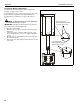
Serial Communications
NOTE: Check with the appropriate automation system vendor
for available drivers and/or software for any external
devices.
Notes:
[PR] = Product ID (CM2C40 = 02)
[AD] = Address (see address description & table)
[CR] = ASCII Carriage Return
[CH] = Check Code
[ST] = Status (see status table)
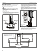
Connections to be made to 9 pin connector as follows:
Communication parameters as specified in ANSI TIA/EIA-485-A:
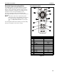
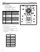
Address Description
Multiple Chief devices can be used on the same network by
setting each device to a different address.
NOTE: All units ship with a default address of 00.
NOTE: Broadcast messages will command all devices on the
same network.
RS-485 REF Pin 7
RS-485 + Pin 9
RS-485 - Pin 8
Baud Rate: 9600
Data Length: 8 Bits
Parity: None
Stop Bit: 1
Flow Control: None
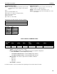
SERIAL CONTROL COMMAND STRING
• Product ID for the CM2C40: 02
• Address controlled by dip switch settings
• Basic Commands available for the CM2C40 in the factory-supplied configuration:
• 03: Cancel Move = >0500037D[Carriage Return]
• 10: Extend to End of Travel = >0500107B0D[Carriage Return]
• 12: Retract to End of Travel = >0500127D0D[Carriage Return]
• Message Data = The data is required for the available commands:
• 03: None
• 10: None
• 12: None
• Check Code is calculated.
For further information, reference the Advanced Programming document and the website calculator.
Start of
Message
(HEX)
Product ID
(HEX)
Address
(HEX)
Command
(HEX)
Message
Data
(HEX)
Check Code
(HEX)
End of Message
(HEX)
> XX XX XX XX XX [Carriage Return]