INSTALLATION INSTRUCTIONS PACI FCI Interactive Flat Panel Upgrade Kits Spanish Product Description German Product Description Portuguese Product Description Italian Product Description Dutch Product Description French Product Description FCI / PACI
FCI / PACI Installation Instructions DISCLAIMER Milestone AV Technologies and its affiliated corporations and subsidiaries (collectively "Milestone"), intend to make this manual accurate and complete. However, Milestone makes no claim that the information contained herein covers all details, conditions or variations, nor does it provide for every possible contingency in connection with the installation or use of this product.
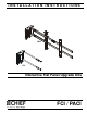
Installation Instructions FCI / PACI DIMENSIONS FCI 140° COVERAGE ANGLE FOR BEST RESULTS: SLIDE THE SENSOR OUT UNTIL THE CORNERS OF THE TV ARE WITHIN THE COVERAGE AREA 0.50 12.
FCI / PACI Installation Instructions DIMENSIONS - continued PACI 14.00 355.7 0.50 12.7 RECOMMENDED SPACING 140° SENSOR COVERAGE SLIDE SENSOR SO THAT CORNERS OF TV ARE INSIDE COVERAGE AREA LIKE SHOWN ABOVE.
Installation Instructions FCI / PACI LEGEND Tighten Fastener Pencil Mark Apretar elemento de fijación Marcar con lápiz Befestigungsteil festziehen Stiftmarkierung Apertar fixador Marcar com lápis Serrare il fissaggio Segno a matita Bevestiging vastdraaien Potloodmerkteken Serrez les fixations Marquage au crayon Loosen Fastener Drill Hole Aflojar elemento de fijación Perforar Befestigungsteil lösen Bohrloch Desapertar fixador Fazer furo Allentare il fissaggio Praticare un foro Beves
FCI / PACI Installation Instructions TOOLS REQUIRED FOR INSTALLATION 1/8" (includedboth models) 3/16" (included FCI only) PARTS FCI Only A (2) ClickConnect 10-24 x 3/8" B (2) #10 Interactive Hardware Kit (PACI Only) D (1) [FCI 3"-5" extension bracket] E (2) [Interactive bar assembly] C (1) 1/8" PACI Only H (1) 1/8" D (1) [PACI 3"-5" extension bracket] G (2) 5/16 x 5/8" F (1) [Sensor assembly] J (1) 3/16" K (1) - Chief Interactive Kit (Both FCI / PACI models) F (1) [Sensor assembly] KA (1)
Installation Instructions FCI / PACI PRE-INSTALLATION INFORMATION Compatibility (F) An up-to-date list of the flat panel TV models recommended for use with Chief’s FCI and PACI interactive kits can be found at www.chiefmfg.com/Interactive-Mounts. The recommended flat panel models all have the same display requirements: • • • (D) Rigid front panel to protect LCD from wear 40" to 55" LED-backlit LCD to reduce interference with the sensor due to excessive heat Bezel depth of 8mm (0.
FCI / PACI 3. Installation Instructions Insert interactive bar assembly (E) into flat panel mount, turning bars until tightened into flat panel mount. (See Figure 4) (back view) 3 (E) Flat panel mount (E) 3 3 2 3 4 (front view) Figure 4 4. Fasten sensor assembly (F) to bars (E) using two 5/16 x 5/8" button head cap screws (G). (See Figure 5) 4 Figure 6 5. Align ClickConnect assembly (E) with the mount, aligning four mounting buttons on assembly with four mounting holes in mount.
Installation Instructions FCI / PACI Holes are provided in the faceplate for use with a padlock or similar locking device, if desired. In addition, the pin and nut may be removed from the upper holes and moved to the lower holes for use as a more permanent locking device. (See Figure 8) To use as a more permanent lock, remove pin and nuts and move to lower holes. 5 CONNECTING FCI/PACI NOTE: Follow instructions in the Quick Start Guide (KE).
FCI / PACI Installation Instructions Sensor Location NOTE: The FCI and PACI may be mounted to the left or right side of a flat panel screen. The green sensor light needs to always be oriented so that it is closest to screen. 1. 3" [76.2mm] Move sensor assembly to the recommended sensor locations noted in Table 1-1, and shown in Dimensions drawings and (See Figure 10) and (See Figure 11).
Installation Instructions 3. FCI / PACI Perform the grid test to see if there are any inconsistencies. a. Open eBeam software (See Figure 13) FAILED grid test Distorted annotation lines a PASSED grid test Figure 13 b. Go to Full Screen view (See Figure 14) b c Figure 15 5. If the grid test has failed, gradually move the sensor assembly in 1/2" increments in both the depth and lateral extension ranges until the grid test is passed. 6.
FCI / PACI Installation Instructions Checking System Diagnostics 1. Right click on the E-Beam icon on the system tray to open the software. 2. Select Interactive Options. (See Figure 16) 3. Select System Preferences. 4. Select Hardware Diagnostics. 5. Record the 3 numbers that appear in Hardware Diagnostics (See Figure 16) 6. Compare hardware diagnostics results to table below.
Installation Instructions FCI / PACI 13
FCI / PACI 14 Installation Instructions
Installation Instructions FCI / PACI 15
FCI / PACI Installation Instructions USA/International Europe Chief Manufacturing, a products division of Milestone AV Technologies 8800-002164 Rev01 2012 Milestone AV Technologies, a Duchossois Group Company www.chiefmfg.com 07/12 Asia Pacific A P F A P F A 6436 City West Parkway, Eden Prairie, MN 55344 800.582.6480 / 952.225.6000 877.894.6918 / 952.894.6918 Franklinstraat 14, 6003 DK Weert, Netherlands +31 (0) 495 580 852 +31 (0) 495 580 845 Office No.