
Operating instructions


Installation Instructions FCI / PACI
9
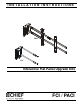
Holes are provided in the faceplate for use with a padlock or
similar locking device, if desired. In addition, the pin and nut may
be removed from the upper holes and moved to the lower holes
for use as a more permanent locking device. (See Figure 8)
Figure 8
7. Fasten sensor assembly (F) to ClickConnect assembly (E)
using two 10-24 x 3/8" button head cap screws (A) and two
#10 flat washers (B). (See Figure 9)
Figure 9
8. Re-attach flat panel TV following instructions contained with
mount.
9. Proceed to Connecting FCI/PACI section.
CONNECTING FCI/PACI
NOTE: Follow instructions in the Quick Start Guide (KE).
IMPORTANT ! : After adding battery (KD) to the stylus
(KB), tighten the cap only to the point of being fingertip-
tight. Overtightening cap may cause the stylus to stop
transmitting signals.
1. Connect flat panel TV to computer.
2. Connect USB cord (KG) from cartridge in sensor assembly
(F) to computer USB port.
3. Insert interactive software CD (KC) into computer, and
follow start-up and operating instructions.
Minimum System Requirements for FCI/PACI
• Windows® System
• Compatible PC with Pentium™ II 400 MHz+
processor and 256 MB RAM
• Windows 2000, XP, Server 2003, Vista, or 7
• 30 MB available hard drive space
• Available USB port
• Macintosh® System
• Power PC®/Intel™ 1.42 GHz+ processor and 1G
RAM
• Mac OS X 10.5 through 10.6
• 25 MB available hard drive space
• Available USB port
Connection Requirement
• The FCI/PACI includes a USB cable.
Screen Recording Requirements
(Currently available only on Windows platform.)
• Pentium™ IV processor
• 1.4GHz, with 512MB RAM
Placement Tips
NOTE: See DIMENSIONS drawing for TV/sensor assembly
placement information.
• The corners of the TV should be positioned within the
fan area extending from the sensor assembly. This fan
area should not exceed 140°.
• Do not put sticky notes, hanging paper, cables, outlets,
or other items inside the capture area.
5
6
To use as a more
permanent lock, remove
pin and nuts and move
to lower holes.
A padlock or bolt may
be placed through latch holes
(F)
7
(A) x 2
(B) x 2
(E)