
Owner manual


Installation Instructions FTR Series
5
6. Repeat Steps 4 and 5 for remaining anchors.
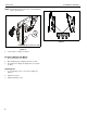
7. Remove and retain anchor screws from anchors (B).
NOTE: Anchors (B) may come with small washers which may
be left on the screw or discarded. These small washers
do NOT replace washers (C).
8. Insert anchor screws through washers (C), FTR (A) and
install into collapsed anchors (B). Tighten until secure.
(See Figure )
Figure 4
Install Display to Mount
NOTE: Proper interface must be attached to display. Follow
instructions included with interface assembly.
1. Open latching flag by rotating flag clockwise on FTR (A).
(See Figure 5)
Figure 5
2. Lift and maneuver display such that all mounting buttons fit
into openings on FTR (A). (See Figure 6)
3. Lower display firmly into place. Ensure each mounting
button has fully seated in the opening (See Figure 6)
4. Close latching flag by rotating flag counterclockwise on FTR
(A). (See Figure 6)
Figure 6
NOTE: Mounting buttons are shown in the 100mm x 100mm
pattern. FTR (A) will also accommodate a 75mm x
75mm pattern. (See Figure 7)
Figure 7
(B)
8
Anchor
(C) x 4
(A)
screws
x 4
1
Latching
flag closed
Latching
flag open
2
3
Display
(A)
4
Latching
flag
Button location for
75mm x 75mm
pattern (4 places)
NOTE: Display not shown for clarity.
Button location
for 100mm x
100mm pattern
(4 places)