INSTALLATION INSTRUCTIONS Instrucciones de instalación Installationsanleitung Instruções de Instalação Istruzioni di installazione Installatie-instructies Instructions d´installation K3G310 K3F220 K3F120 K3G120 K3G220 Kontour™ Array Arm Series Spanish Product Description German Product Description Portuguese Product Description Italian Product Description Dutch Product Description French Product Description K3 Series
K3 Series Installation Instructions DISCLAIMER Milestone AV Technologies and its affiliated corporations and subsidiaries (collectively "Milestone"), intend to make this manual accurate and complete. However, Milestone makes no claim that the information contained herein covers all details, conditions or variations, nor does it provide for every possible contingency in connection with the installation or use of this product.
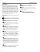
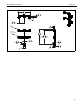
Installation Instructions K3 Series DIMENSIONS K3G310 1.77 45.0 15° MAX ANGLE 25.62 650.7 MAX. DISTANCE BETWEEN MONITORS 17.71 449.8 MIN. DISTANCE BETWEEN MONITORS 55.93 1420.6 1.21 30.6 VESA 100 X 100 75 X 75 COMPATIBLE INTERFACES TILT ADJUSTMENT +/-10 20.87 530.0 TILT ADJUSTMENT +/-12 0.25 6.4 BASE THICKNESS 7.55 191.8 18.291 464.5 MAX. MONITOR CENTER HEIGHT FROM SURFACE TILT ADJUSTMENT +/-12 2.43 61.6 COLUMN WIDTH 4.94 125.5 MAX. SURFACE DEPTH 2.27 57.7 COLUMN DEPTH 2.28 57.9 7.03 178.
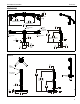
K3 Series Installation Instructions DIMENSIONS (CONTINUED) K3G120 1.21 30.6 VESA 100 X 100 75 X 75 COMPATIBLE 38.81 985.8 TILT ADJUSTMENT +/-10 DEGREES 36.35 923.4 MAX. MONITOR CENTER HEIGHT FROM SURFACE 2.43 61.6 COLUMN WIDTH 18.35 466.2 0.25 6.4 BASE THICKNESS 2.27 57.7 COLUMN DEPTH 4.94 125.5 MAX. SURFACE DEPTH 7.55 191.8 K3F220 2.28 57.9 7.02 178.2 34.02 864.1 1.60 40.6 15° MAX ANGLE 14.66 372.4 MAX DISTANCE BETWEEN MONITORS 1.21 30.
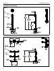
Installation Instructions K3G220 K3 Series 34.02 864.1 1.60 40.6 15° MAX ANGLE 14.66 372.4 MAX DISTANCE BETWEEN MONITORS 1.21 30.6 VESA 100 X 100 75 X 75 COMPATIBLE INTERFACE TILT ADJUSTMENT +/-12 38.81 985.8 36.04 915.3 MAX. MONITOR CENTER HEIGHT FROM SURFACE 0.25 6.4 BASE THICKNESS 7.55 191.8 2.43 61.6 COLUMN WIDTH 2.27 57.7 COLUMN DEPTH 7.03 178.5 2.28 57.
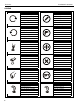
K3 Series Installation Instructions LEGEND 6 Tighten Fastener Pencil Mark Apretar elemento de fijación Marcar con lápiz Befestigungsteil festziehen Stiftmarkierung Apertar fixador Marcar com lápis Serrare il fissaggio Segno a matita Bevestiging vastdraaien Potloodmerkteken Serrez les fixations Marquage au crayon Loosen Fastener Drill Hole Aflojar elemento de fijación Perforar Befestigungsteil lösen Bohrloch Desapertar fixador Fazer furo Allentare il fissaggio Praticare un foro Be
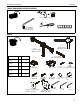
Installation Instructions K3 Series TOOLS REQUIRED FOR INSTALLATION 1/2" (for K3G mounts only) #2 5/16" (included) 3/16" (included) 5/32" (included) PARTS C (1) [table top base] (K3F models only) A (1) [array assembly] (K3G310 shown) B B (see table) [cable management cover] H-M hardware K3F120 2 8 K3G120 2 8 K3F220 6 16 K3G220 6 16 K3G310 3 12 D (1) [column cap] H (see table) M4x30mm N (1) [grommet screw and base] (K3G models only) J (see table) M4x20mm E (1) [base cover] G (
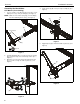
K3 Series Installation Instructions Assembly And Installation 4. Snap column cap (D) onto top of array assembly (A). (See Figure 3) K3F Mounts (Free-standing) 1. Use four 1/4-20 x 1 1/4" flat head cap screws (F) to secure table top base (C) to array assembly (A). (See Figure 1) NOTE: Make sure front of base (long legs) is on the display side when attaching base to array. (See Figure 1) (D) (A) 4 (A) front of base Figure 3 (C) 5. 1 Apply bumpers (G) to underside of table top base (C).
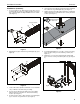
Installation Instructions K3 Series K3G Mounts (Grommet) 1. Use four 1/4-20 x 1 1/4" flat head cap screws (F) to secure grommet plate (P) to array assembly (A). Make sure longer legs of grommet plate are aligned with the front of column. (See Figure 5) 6. Insert grommet screw (N) through grommet hole and thread into center hole of grommet plate (P). (See Figure 7) 7. Tighten grommet screw (N) until grommet base is tightened against underside of desk and mount is securely mounted to desk.
K3 Series Installation Instructions 10. Snap column cap (D) onto top of array assembly (A). (See Figure 9) 2 (K) x 2 (D) (A) 10 Figure 9 Center faceplate (array stand not shown for clarity) Display Installation Figure 10 WARNING: Exceeding the weight capacity can result in 3.
Installation Instructions K3 Series Recessed Mounting Holes NOTE: If faceplate does not fit into recessed area of display, proceed with the steps in this section. 1. Determine depth of recessed mounting holes relative to back surface of display (against which faceplate will contact). 2. Select proper length spacer and screw from table below: Center faceplate (array stand not shown for clarity) 3 (J or H) x 2 NOTE: All spacers used should be the same length.
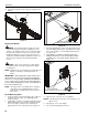
K3 Series 2. Installation Instructions When arms are at desired pivot position, lock pivot position by tightening pivot adjustment screws using 5/16" hex key (N). (See Figure 15) Arm Extension (K3G310 only) NOTE: For smaller displays or if converting to a 2x1 array, faceplate assemblies may be removed and reattached to fixed part of the arm. See Faceplate Assembly Section - Outside Faceplates for details. 2 pivot adjustment screws 1.
Installation Instructions K3 Series Outside Faceplates (K3G310 only) Lateral Shift (On Fixed Arm) 1. NOTE: The procedure below applies when the outside 2. Remove hex head bolt from bottom of faceplate assembly. (See Figure 19) faceplates have been attached to the fixed arm. If outside faceplates are still attached to extension arms, use the extension arms for lateral shift. Slide out removable plate from bottom of faceplate assembly. (See Figure 19) 1.
K3 Series Installation Instructions Center Faceplate(s) Cable Management Pitch 1. Route cables from display through cable management covers (B) as desired. (See Figure 24) and (See Figure 25) 2. Install cable management covers (B) onto array (A). (See Figure 24) and (See Figure 25) 1. Loosen knob on side of center faceplate assembly. (See Figure 23) 2. Adjust pitch as desired. (See Figure 23) 3. Tighten knob to secure desired pitch position.
Installation Instructions K3 Series 15
K3 Series Installation Instructions USA/International Europe Chief Manufacturing, a products division of Milestone AV Technologies 8800-002257 Rev01 2013 Milestone AV Technologies, a Duchossois Group Company www.chiefmfg.com 04/13 Asia Pacific A P F A P F A 6436 City West Parkway, Eden Prairie, MN 55344 800.582.6480 / 952.225.6000 877.894.6918 / 952.894.6918 Franklinstraat 14, 6003 DK Weert, Netherlands +31 (0) 495 580 852 +31 (0) 495 580 845 Office No.