INSTALLATION INSTRUCTIONS Instrucciones de instalación Installationsanleitung Instruções de Instalação Istruzioni di installazione Installatie-instructies Instructions d´installation Triple/Dual Array Table Top Stand Spanish Product Description German Product Description Portuguese Product Description Italian Product Description Dutch Product Description French Product Description K3F310
Installation Instructions K3F310 DISCLAIMER WARNING: Failure to read, thoroughly understand, and Milestone AV Technologies and its affiliated corporations and subsidiaries (collectively "Milestone"), intend to make this manual accurate and complete. However, Milestone makes no claim that the information contained herein covers all details, conditions or variations, nor does it provide for every possible contingency in connection with the installation or use of this product.
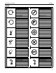
Installation Instructions K3F310 LEGEND Tighten Fastener Pencil Mark Apretar elemento de fijación Marcar con lápiz Befestigungsteil festziehen Stiftmarkierung Apertar fixador Marcar com lápis Serrare il fissaggio Segno a matita Bevestiging vastdraaien Potloodmerkteken Serrez les fixations Marquage au crayon Loosen Fastener Drill Hole Aflojar elemento de fijación Perforar Befestigungsteil lösen Bohrloch Desapertar fixador Fazer furo Allentare il fissaggio Praticare un foro Bevestigi
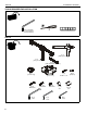
K3F310 Installation Instructions TOOLS REQUIRED FOR INSTALLATION #2 5/16" (included) 3/16" (included) 5/32" (included) PARTS C (1) [table top base] A (1) [array assembly] B (3) [cable management cover] D (1) [column cap] H (12) M4x30mm N (1) 5/16" 4 E (1) [base cover] J (12) M4x20mm K (12) M4x12mm P (1) 3/16" F (4) 1/4-20 x 1 1/4 L (12) 3/8" G (6) [bumper] M (12) 3/4" Q (1) 5/32"
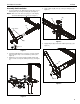
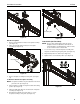
Installation Instructions K3F310 Assembly And Installation 1. 4. Snap column cap (D) onto top of array assembly (A). (See Figure 3) Use four 1/4-20 x 1 1/4" flat head cap screws (F) to secure table top base (C) to array assembly (A). (See Figure 1) NOTE: Make sure front of base (long legs) is on the display side when attaching base to array. (See Figure 1) (D) (A) 4 (A) front of base (C) Figure 3 5. 1 Apply bumpers (G) to underside of table top base (C). (See Figure 4) (F) x 4 Figure 1 2.
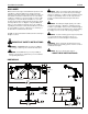
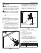
K3F310 Installation Instructions 3. Display Installation WARNING: Exceeding the weight capacity can result in serious personal injury or damage to equipment! It is the installer’s responsibility to make sure the combined weight of all components located on the K3F310 up to (and including) the display does not exceed 15 lbs (6.8 kg) per display. Pick up and align display so that screws (K) (installed on the back of the display in the previous step) fit into the mounting holes on the faceplate.
Installation Instructions K3F310 CAUTION: Using screws of improper size may damage Center faceplate (array stand not shown for clarity) your display! Proper screws will easily and completely thread into display mounting holes. 3. Using Phillips screwdriver, carefully install two selected screws (J or H) through selected spacers (L or M) into the upper mounting holes on the display. Thread screws completely into display, then back out 3 complete turns. (See Figure 7) 4.
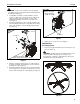
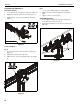
K3F310 2. Installation Instructions When arms are at desired pivot position, lock pivot position by tightening pivot adjustment screws using 5/16" hex key (N). (See Figure 10) Arm Extension NOTE: For smaller displays or if converting to a 2x1 array, faceplate assemblies may be removed and reattached to fixed part of the arm. See Faceplate Assembly Section - Outside Faceplates for details. 2 pivot adjustment screws 1. Turn arm extension adjustment knob counter-clockwise on arm to be adjusted.
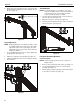
Installation Instructions K3F310 4 1 2 3 5 removable plate 6 Figure 13 Figure 15 Outside Faceplates Lateral Shift (On Fixed Arm) 1. Remove hex head bolt from bottom of faceplate assembly. (See Figure 14) 2. Slide out removable plate from bottom of faceplate assembly. (See Figure 14) NOTE: The procedure below applies when the outside faceplates have been attached to the fixed arm. If outside faceplates are still attached to extension arms, use the extension arms for lateral shift. 1.
K3F310 Installation Instructions Pitch/Roll/Yaw Adjustment Roll Outside Faceplates 1. Loosen screws holding display to faceplate slightly. 1. Loosen knob on top of faceplate assembly. (See Figure 17) 2. Adjust roll position as the mounting holes on faceplate allow. 2. Adjust pitch, roll and/or yaw as desired. (See Figure 17) 3. Tighten screws to lock roll position. 3. Tighten knob to secure desired faceplate position. (See Figure 17) 1 3 Cable Management 1.
Installation Instructions K3F310 11
K3F310 Installation Instructions USA/International Europe Chief Manufacturing, a products division of Milestone AV Technologies 8800-002254 Rev00 2012 Milestone AV Technologies, a Duchossois Group Company www.chiefmfg.com 10/12 Asia Pacific A P F A P F A 6436 City West Parkway, Eden Prairie, MN 55344 800.582.6480 / 952.225.6000 877.894.6918 / 952.894.6918 Franklinstraat 14, 6003 DK Weert, Netherlands +31 (0) 495 580 852 +31 (0) 495 580 845 Office No.