INSTALLATION INSTRUCTIONS Istruzioni di installazione Installatie-instructies Instructions d´installation Instrucciones de instalación Installationsanleitung Instruções de Instalação K4G210 K4G310 Kontour™ Articulating Array Arm Grommet Series Spanish Product Description German Product Description Portuguese Product Description Italian Product Description Dutch Product Description French Product Description K4G210-310
K4G210-310 Installation Instructions DISCLAIMER Milestone AV Technologies and its affiliated corporations and subsidiaries (collectively “Milestone”), intend to make this manual accurate and complete. However, Milestone makes no claim that the information contained herein covers all details, conditions or variations, nor does it provide for every possible contingency in connection with the installation or use of this product.
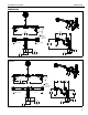
Installation Instructions K4G210-310 DIMENSIONS K4G210 20° MAX ANGLE 16.20 411.5 EXTENSION 37.13 943.2 MAX DISTANCE TILT ADJUSTMENT ±12° VESA 100 X 100 75 X 75 COMPATIBLE INTERFACES TILT ADJUSTMENT ±12° 15.28 388.2 + 3.00 [76.2] - 3.75 [95.3] 2.27 57.6 4.94 125.5 MAX SURFACE DEPTH 7.74 196.7 7.13 181.1 7.11 180.7 K4G310 20° MAX ANGLE 24.12 612.7 16.20 411.5 EXTENSION 48.36 1228.4 MAX DISTANCE TILT ADJUSTMENT ±12° TILT ADJUSTMENT ±12° TILT ADJUSTMENT ±12° 7.15 181.
K4G210-310 Installation Instructions LEGEND 4 Tighten Fastener Pencil Mark Apretar elemento de fijación Marcar con lápiz Befestigungsteil festziehen Stiftmarkierung Apertar fixador Marcar com lápis Serrare il fissaggio Segno a matita Bevestiging vastdraaien Potloodmerkteken Serrez les fixations Marquage au crayon Loosen Fastener Drill Hole Aflojar elemento de fijación Perforar Befestigungsteil lösen Bohrloch Desapertar fixador Fazer furo Allentare il fissaggio Praticare un foro B
Installation Instructions K4G210-310 TOOLS REQUIRED FOR INSTALLATION 1/2” #2 5/16” (included) 3/16” (included) 5/32” (included) 1/8” (included) PARTS Hardware bag (parts numbered on bag as shown) A1 (2) 3/8-16 x 2 3/4” A2 (2) 3/8” C (4) 1/4-20 x 1 1/4” E2 (4) F1 (1) E1 (4) [tie mount] #10-24 3/8” 1/8” *8 for K4G210 and 12 for K4G310 J (2) (K4G310 only) [channel attachment] K (1) [column cap] B1 (2) 1/4-20 x 1/2” D1 (2) #10-32 x 1/2” F2 (1) 3/16” B2 (2) 1/4” G (2) [handle clamp] D2 (2) #10-
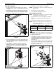
K4G210-310 Installation Instructions Assembly And Installation 1. Use four 1/4-20 x 1 1/4” flat head cap screws (C) to secure grommet plate (U) to column (CC). Make sure longer legs of grommet plate are aligned with the front of column. (See Figure 1) 6. Insert grommet screw (T) through grommet hole and thread into center hole of grommet plate (U). (See Figure 3) 7. Tighten grommet screw (T) until grommet base is tightened against underside of desk and mount is securely mounted to desk.
Installation Instructions K4G210-310 10. Loosely install two 1/4-20 x 1/2” socket head carriage screws (B1) through mounting holes on column arm (Z) bracket and into 1/4” square nuts (B2). (See Figure 5) (K4G210 shown) (A1) x 2 14 11. Slide column arm (Z) bracket into column (CC) until desired mounting height is reached. (See Figure 5) (B2) x 2 11 (Z) 10 (A2) x 2 Figure 7 (B1) x 2 (CC) 15. Hang array center (AA or BB) onto column arm (Z) faceplate.
K4G210-310 Installation Instructions (K4G210 shown) 20. Use two #10-32 x 1/2” Phillips pan machine screws (D1) and two handle clamps (G) to secure handle (H) to array center (AA or BB). (See Figure 12) (AA) (K4G310 shown) (Z) (G) x 2 (D2) x 2 16 Figure 9 17. (K4G310 only) Insert two channel attachments (J) into back of array center (BB). Attachments must be turned horizontally in order to fit into channel.
Installation Instructions K4G210-310 Flush Mounting Holes 5. 1. Position faceplate in desired mounting position. Adjust as required before proceeding. See Height Adjustment Section for details. NOTE: If roll adjustment is desired for center faceplate, do not Using Phillips screwdriver, carefully install two M4 x 12mm Phillips pan machine screws (P) into the upper mounting holes on the display. Thread screws completely into display, then back out 3 complete turns. (See Figure 13) 6.
K4G210-310 5. 6. Installation Instructions Slide two remaining selected spacers (Q or R) in between faceplate and display, positioning them over the lower two mounting holes. (See Figure 16) Install two remaining selected screws (N or M) through lower two mounting holes on faceplate, selected spacers (Q or R) into the lower mounting holes on the display. (See Figure 16) Pivot Adjustment (Column Arm) 1. Use handle to extend or collapse column arm (Z) as desired. (See Figure 18) 2.
Installation Instructions K4G210-310 Faceplate Assembly Removal Lateral Shift 1. Remove hex head bolt from bottom of faceplate assembly. (See Figure 20) 1. Loosen knob on top of faceplate assembly until faceplate can slide freely along array. (See Figure 22) 2. Slide out removable plate from bottom of faceplate assembly. (See Figure 20) 2. Adjust lateral position as desired. (See Figure 22) 3. Tighten knob to secure lateral position.
K4G210-310 Installation Instructions Cable Management 3. Route cables along mounting arms. (See Figure 26) 1. Route cables from display through cable management covers (V) as desired. (See Figure 24) 4. Use cable ties (not included) to secure cables to tie clips (E1). (See Figure 26) 2. Install cable management covers (V) onto array arms (X and Y). (See Figure 24) NOTE: Leave enough slack in the cables so that arm may still swing without resistance from the cables.
Installation Instructions K4G210-310 13
K4G210-310 14 Installation Instructions
Installation Instructions K4G210-310 15
K4G210-310 Installation Instructions USA/International Europe Chief Manufacturing, a products division of Milestone AV Technologies 8800-002371 Rev02 2013 Milestone AV Technologies, a Duchossois Group Company www.chiefmfg.com 06/13 Asia Pacific A P F A P F A 6436 City West Parkway, Eden Prairie, MN 55344 800.582.6480 / 952.225.6000 877.894.6918 / 952.894.6918 Franklinstraat 14, 6003 DK Weert, Netherlands +31 (0) 495 580 852 +31 (0) 495 580 845 Office No.