
Operating instructions


K4G210-310 Installation Instructions
12
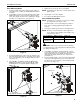
Cable Management
1. Route cables from display through cable management
covers (V) as desired. (See Figure 24)
2. Install cable management covers (V) onto array arms (X
and Y). (See Figure 24)
Figure 24
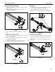
Cable Management - Clips
1. Use two #10-24 x 3/8” button head cap screws (E2) to
attach two tie mounts (E1) to upper mounting arm. (See
Figure 25)
2. Use two #10-24 x 3/8” button head cap screws (E2) to
attach two tie mounts (E1) to lower mounting arm. (See
Figure 25)
Figure 25
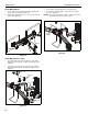
3. Route cables along mounting arms. (See Figure 26)
4. Use cable ties (not included) to secure cables to tie clips
(E1). (See Figure 26)
NOTE: Leave enough slack in the cables so that arm may still
swing without resistance from the cables.
Figure 26
(V) x 2
1
1
1
2
2
(K4G210 shown as example)
(E2) x 2
1
(E1) x 2
(E2) x 2
2
(E1) x 2
cable
(example)
cable ties (not included)
4