INSTALLATION INSTRUCTIONS Istruzioni di installazione Installatie-instructies Instructions d´installation Instrucciones de instalación Installationsanleitung Instruções de Instalação K4G410 K4G420 K4G510 K4G520 K4G610 K4G620 Large Kontour™ Articulating Array Arm Grommet Series Spanish Product Description German Product Description Portuguese Product Description Italian Product Description Dutch Product Description French Product Description K4G4X-5X-6X Series
K4G4X-5X-6X Series Installation Instructions DISCLAIMER Milestone AV Technologies and its affiliated corporations and subsidiaries (collectively “Milestone”), intend to make this manual accurate and complete. However, Milestone makes no claim that the information contained herein covers all details, conditions or variations, nor does it provide for every possible contingency in connection with the installation or use of this product.
Installation Instructions K4G4X-5X-6X Series DIMENSIONS K4G410 80.7 3.5 15.6 12.0 EXTENSION MINIMUM COLUMN CENTER TO CENTER DISTANCE IS DEPENDANT ON MONITOR WEIGHT AND WIDTH 1.0 VESA 100 X 100, 75 X 75 COMPATIBLE INTERFACE 12 TILT ADJUSTMENT 13.3 18.1 MAX MONITOR HEIGHT 5.0 MAX SURFACE DEPTH 7.7 7.1 K4G510 96.3 7.6 23.3 12.0 EXTENSION MINIMUM COLUMN CENTER TO CENTER DISTANCE IS DEPENDANT ON MONITOR WEIGHT AND WIDTH 1.0 VESA 100 X 100, 75 X 75 COMPATIBLE INTERFACE 12 TILT ADJUSTMENT 7.
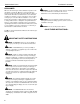
K4G4X-5X-6X Series Installation Instructions DIMENSIONS (CONTINUED) K4G610 109.1 14.2 32.1 12.0 EXTENSION MINIMUM COLUMN CENTER TO CENTER DISTANCE IS DEPENDANT ON MONITOR WEIGHT AND WIDTH 1.0 18.1 MAX MONITOR HEIGHT 5.0 MAX SURFACE DEPTH 7.7 COMPATIBLE INTERFACE 12 TILT ADJUSTMENT 13.3 7.1 80.7 K4G420 3.5 15.6 12.0 EXTENSION MINIMUM COLUMN CENTER TO CENTER DISTANCE IS DEPENDANT ON MONITOR WEIGHT AND WIDTH 38.8 43.6 MAX MONITOR HEIGHT 1.0 7.
K4G4X-5X-6X Series Installation Instructions DIMENSIONS (CONTINUED) K4G520 96.3 7.6 23.3 12.0 EXTENSION MINIMUM COLUMN CENTER TO CENTER DISTANCE IS DEPENDANT ON MONITOR WEIGHT AND WIDTH 38.8 43.6 MAX MONITOR HEIGHT 1.0 VESA 100 X 100, 75 X 75 COMPATIBLE INTERFACE 12 TILT ADJUSTMENT 7.1 5.0 MAX SURFACE DEPTH 7.7 K4G620 109.1 14.2 32.1 12.0 EXTENSION MINIMUM COLUMN CENTER TO CENTER DISTANCE IS DEPENDANT ON MONITOR WEIGHT AND WIDTH 38.8 1.0 COMPATIBLE INTERFACES 12 TILT ADJUSTMENT 5 7.
Installation Instructions K4G4X-5X-6X Series LEGEND Tighten Fastener Pencil Mark Apretar elemento de fijación Marcar con lápiz Befestigungsteil festziehen Stiftmarkierung Apertar fixador Marcar com lápis Serrare il fissaggio Segno a matita Bevestiging vastdraaien Potloodmerkteken Serrez les fixations Marquage au crayon Loosen Fastener Drill Hole Aflojar elemento de fijación Perforar Befestigungsteil lösen Bohrloch Desapertar fixador Fazer furo Allentare il fissaggio Praticare un for
Installation Instructions K4G4X-5X-6X Series TOOLS REQUIRED FOR INSTALLATION 1/2” 5/16” (included) 3/16” (included) 5/32” (included) 1/8” (included) 3/32” (included) #2 PARTS (Refer to Table 1 for quantities of parts) A #10-32 x 5/16” B #10-32 x 1” J [Array plate] H [Array connector] F [Column arm- single tier] P [9 1/2” cable cover] M [Grommet screw and base] N [Grommet plate] R - Display Mounting Hardware D #8-32 x 1/2” E 1/4-20 x 1 1/4” AA [Left array arm] L [Base cover] K [Column cap]
K4G4X-5X-6X Series Installation Instructions Table 1: Parts ITEM K4G410 K4G510 K4G610 K4G420 K4G520 K4G620 A Screw, Button Head Cap, #10-32 x 5/16” 4 4 4 8 8 8 B Screw, Button Head Cap, #10-32 x 1" 4 4 4 8 8 8 C Screw, Button Head Cap, #10-24 x 1 1/8” 4 4 4 8 8 8 D Screw, Flat Head Cap, #8-32 x 1/2” 4 4 4 8 8 8 8 E Screw, Flat Head Cap, 1/4-20 x 1 1/4” 8 8 8 8 8 F Column Arm - Single Tier Models 2 2 2 - - - G Column Arm - Dual Tier Models - - - 2 2 2
Installation Instructions K4G4X-5X-6X Series Assembly And Installation 1. WARNING: The K4G4X-5X-6X Series mounts were Use four 1/4-20 x 1 1/4” flat head cap screws (E) to secure grommet plate (N) to column (F or G). Make sure longer legs of grommet plate are aligned with the front of column. (See Figure 1) designed to mount displays between 19-23” in width. Do NOT install displays smaller than 19" in width or larger than 23" in width! NOTE: Column 1 shows monitor “width” not diagonal size.
K4G4X-5X-6X Series 9. Installation Instructions Carefully manipulate base cover (L) to create an opening large enough to wrap cover around array column. (See Figure 3) 10. Wrap base cover (L) around column and slide it down until base cover fits securely onto grommet plate (N). (See Figure 3) connector plate to use for K4G610/620 connector plate to use for K4G410/420/510/520 14 (AA/BB) mounting tab 10 9 faceplate (L) (N) 9 Figure 3 11.
Installation Instructions K4G4X-5X-6X Series 16. Insert array connector (H) [K4G410/420 models] or connectors pre-installed on both end of center plates (CC or DD) into left and right array arm openings. (See Figure 7) (front view) K4G410-420 17. Slide array plates (J) into grooves on back of array arms, lining up holes on plates with holes in arms.
K4G4X-5X-6X Series Installation Instructions 20. Use four #10-32 x 1" button head cap screws (B) to secure two handles (EE) to array arms (AA and BB) or K4G6X center plate (DD). (See Figure 9) Display Installation NOTE: Handles attach to right and left arrays (AA and BB) for WARNING: Exceeding the weight capacity can result in all K4G4 and K4G5 models. Handles attach to K4G6X center plate for K4G6X models.
Installation Instructions 4. K4G4X-5X-6X Series Using Phillips screwdriver, install two M4x12 mm Phillips pan machine screws (R3) through the lower mounting holes on faceplate into the display. (See Figure 12) 4. Pick up and align display so that screws (R1 or R2) (installed on the back of the display in the previous step) fit into the mounting holes on the faceplate. Lower the display firmly into place.
K4G4X-5X-6X Series Installation Instructions Adjustments 1 Pivot Adjustment (Column Arm) 1. Use handles (EE) to extend or collapse column arms as desired. (See Figure 15) 2. (Optional) Loosen or tighten column arm pivot tension screws as desired to increase or decrease pivot tension. (See Figure 15) 3 (K4G610 shown) arms extended 2 arms collapsed Figure 16 Faceplate Assembly Removal 1. Remove socket head cap screw from bottom of faceplate assembly. (See Figure 17) 2.
Installation Instructions K4G4X-5X-6X Series To Reattach Faceplate Assembly Pitch/Roll/Yaw Adjustment 4. Place faceplate assembly on array arm at desired mounting position. (See Figure 18) 1. Loosen knob on top of faceplate assembly. (See Figure 20) 2. Adjust pitch, roll and/or yaw as desired. (See Figure 20) 5. Slide removable plate back into slot at bottom of faceplate assembly. (See Figure 18) 3. Tighten knob to secure desired faceplate position. (See Figure 20) 6.
K4G4X-5X-6X Series Installation Instructions 1 (Q) x 2 1 (Q) x 3 K4G610/620 2 (Q) x 2 K4G410/420 2 (Q) x 2 1 (Q) x 4 2 (Q) x 2 K4G510/520 Figure 21 Cable Management 1. Install 4 1/2” cable covers (Q) to array arms. (See Figure 21) 2. Install two 4 1/2” cable covers (Q) to single tier column arms (F) or four 9 1/2” cable covers (P) to dual tier column arms (G). (See Figure 21) or (See Figure 22) 3. Route cables from display through cable management covers (Q) on array arms as desired.
Installation Instructions K4G4X-5X-6X Series Display Leveling For Sag to the Inside If the array sags after attaching displays, adjust the connection point to the arms until an even mount is achieved. Refer to the appropriate section depending on whether the array sags to the inside or the outside. (See Figure 24) 4. Loosen two screws holding column arms to outer array arms. (See Figure 26) 5.
K4G4X-5X-6X Series 18 Installation Instructions
Installation Instructions K4G4X-5X-6X Series 19
K4G4X-5X-6X Series Installation Instructions USA/International Europe Chief, a products division of Milestone AV Technologies 8800-002432 Rev00 2014 Milestone AV Technologies www.chiefmfg.com 04/14 Asia Pacific A P F A P F A 6436 City West Parkway, Eden Prairie, MN 55344 800.582.6480 / 952.225.6000 877.894.6918 / 952.894.6918 Franklinstraat 14, 6003 DK Weert, Netherlands +31 (0) 495 580 852 +31 (0) 495 580 845 Office No.