INSTALLATION INSTRUCTIONS Instrucciones de instalación Installationsanleitung Instruções de Instalação KTC-220 Istruzioni di installazione Installatie-instructies Instructions d´installation KTC-225 KTC-320 KTC-230 KTC-325 KTC-330 KTC-440 KTC-445 Horizontal and Vertical Desk Clamp Stands Spanish Product Description German Product Description Portuguese Product Description Italian Product Description Dutch Product Description French Product Description KTC SERIES
KTC SERIES Installation Instructions DISCLAIMER WARNING: Failure to read, thoroughly understand, and Milestone AV Technologies and its affiliated corporations and subsidiaries (collectively "Milestone"), intend to make this manual accurate and complete. However, Milestone makes no claim that the information contained herein covers all details, conditions or variations, nor does it provide for every possible contingency in connection with the installation or use of this product.
Installation Instructions KTC SERIES DIMENSIONS - CONTINUED 17.24 437.8 2.25 57.2 3.63 92.1 6.87 174.6 30.51 774.8 1.96 49.8 1.90 48.3 13.25 336.6 .25 6.4 3.75 95.3 .50 [12.7] MIN 3.00 [76.2] MAX 2.75 69.9 KTC-225 3.63 92.1 3.26 82.7 2.25 57.2 5.50 139.6 1.90 29.75 755.6 .25 3.75 95.3 .50 [12.7] MIN 3.00 [76.2] MAX 2.75 69.
KTC SERIES Installation Instructions DIMENSIONS - CONTINUED 3.63 92.1 20.80 528.3 2.25 57.2 8.13 206.5 37.14 943.3 1.96 49.8 13.25 336.6 1.90 48.3 .25 6.4 3.75 95.3 .50 [12.7] MIN 3.00 [76.2] MAX 2.75 69.9 KTC-320 3.63 92.1 26.90 683.4 2.25 57.2 10.51 [267.0] 47.70 [1211.6] 1.96 49.8 13.25 336.6 1.90 48.3 .25 6.4 3.75 95.3 .50 [12.7] MIN 3.00 [76.2] MAX 2.75 69.
Installation Instructions KTC SERIES DIMENSIONS - CONTINUED 20.80 528.3 3.63 92.1 2.25 57.2 8.13 206.5 37.14 943.3 1.96 49.8 27.25 692.2 1.90 48.3 .25 6.4 .50 [12.7] MIN 3.00 [76.2] MAX 3.75 95.3 2.75 69.9 KTC-330 13.68 347.4 3.63 92.1 2.25 57.2 5.88 149.2 23.83 605.4 1.96 49.8 27.25 692.2 .25 6.4 3.75 95.3 .50 [12.7] MIN 3.00 [76.2] MAX 2.75 69.
KTC SERIES Installation Instructions DIMENSIONS - CONTINUED 17.24 437.8 3.63 92.1 2.25 57.2 6.87 174.6 30.51 774.8 1.96 49.8 27.25 692.2 .25 6.4 3.75 95.3 .50 [12.7] MIN 3.00 [76.2] MAX KTC-445 6 2.75 69.
Installation Instructions KTC SERIES LEGEND Tighten Fastener Pencil Mark Apretar elemento de fijación Marcar con lápiz Befestigungsteil festziehen Stiftmarkierung Apertar fixador Marcar com lápis Serrare il fissaggio Segno a matita Bevestiging vastdraaien Potloodmerkteken Serrez les fixations Marquage au crayon Loosen Fastener Drill Hole Aflojar elemento de fijación Perforar Befestigungsteil lösen Bohrloch Desapertar fixador Fazer furo Allentare il fissaggio Praticare un foro Beves
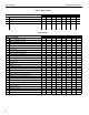
KTC SERIES Installation Instructions Table 1: Monitor Limits MONITOR LIMITS By MODEL DESCRIPTION 220 225 230 320 325 330 440 445 Weight 35 lbs 35 lbs 35 lbs 30 lbs 30 lbs. 20 lbs 30 lbs 30 lbs Max Screen Width 22.7" 30" N/A 18" 24.5" 18" 22.7" 30" Max Screen Height 28" 28" 19.3" 28" 28" 18.5" 18.5" 18.
Installation Instructions KTC SERIES TOOLS REQUIRED FOR INSTALLATION 5/32" (included) #2 3/16" (included with 230 model only) 7/32" (included) PARTS (REFER TO TABLE 2 FOR QUANTITIES) B C A F 14" E 8" D J 7/32" H K 3/16" Q P M4 X 12 U M4 X 20 V G 28" L M 5/32" R M4 X 30 W S 3/4" N T 3/8" X Y 9
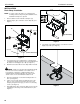
KTC SERIES Installation Instructions INSTALLATION Desk Clamp Installation NOTE: In order to reduce the chance of scratching to the mounting surface, bumpers may be installed. However, installation of bumpers is optional. 1. Remove adhesive from underside of bumpers (H). 2. Attach bumpers (H) to underside of desk clamp (D). (See Figure 1) 6 7 (D) 2 5 (H) x 6 (behind desk) 3 (W) x 1 Figure 2 8. Turn clamp screw until the clamp is secured to the desk as tightly as possible.
Installation Instructions KTC SERIES Mount Assembly KTC-220, 225, 320, 325, 330, 440 and 445 Assembly KTC-230 Assembly 1. Assemble pole clamp back (M) to pole mount front using two washers (X) and two 1/4-20 x 3/4" button head cap screws (U) using a 5/32" hex key (J). (See Figure 6) 1. Place front pole clamp with Centris Head (C) against pole (G) in approximate mounting location. 2. 2.
KTC SERIES Installation Instructions Attach Centris Head to Recessed Mount Display (P) x 2 1 NOTE: Refer to Table 1 to select the applicable screw and spacer combination. 1. Uninstall end lock using the 5/32" hex key (J). (See Figure 10) 2. Slide Centris head off array rail. (See Figure 11) Centris Head Square Nut Display Figure 7 End Lock Display Figure 10 2 2 Centris head Centris Head Figure 8 Figure 11 Display Centris Head 3 (P) x 2 Figure 9 12 3.
Installation Instructions 6 KTC SERIES (Q or R) x 4 End Lock Centris Head 4 (S or T) x 4 End Lock Retaining Screw Display Centris Head Figure 14 ADJUSTMENTS Figure 12 7. Slide display with Centris bracket onto array rail. (See Figure 13) NOTE: Repeat previous steps for each additional display. 8. Reinstall end locks into mounting rail using the 5/32" hex key (J) (See Figure 14).
KTC SERIES Installation Instructions 4. Display Pitch and Roll Adjustment To adjust display pitch or roll position: 1. Loosen Centris bracket front adjustment knob. (See Figure 16) 2. Tilt display up or down, or adjust display roll left or right until properly positioned. 3. Tighten Centris bracket front adjustment knob. Pitch/Roll Adjustment Knob Figure 16 CABLE MANAGEMENT The KTC Series mount includes cable management features used to properly route and secure display cables.
Installation Instructions KTC SERIES 15
KTC SERIES Installation Instructions USA/International Europe Chief Manufacturing, a products division of Milestone AV Technologies 8834-000008 RevC 2010 Milestone AV Technologies, a Duchossois Group Company www.chiefmfg.com 03/10 Asia Pacific A P F A P F A 8401 Eagle Creek Parkway, Savage, MN 55378 800.582.6480 / 952.894.6280 877.894.6918 / 952.894.6918 Fellenoord 130 5611 ZB EINDHOVEN, The Netherlands +31 (0)40 2668620 +31 (0)40 2668615 Office No.