
Instruction manual


Installation Instructions LBM Series
13
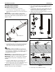
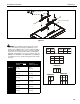
Figure 7
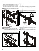
6. Use four 5/16-18 x 3/4" button head flange screws (BB) to
secure each attached clamp bracket (P) to each quick
connect base (Q). (See Figure 8)
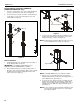
Figure 8
NOTE: If rails must be installed over cable management holes
on column, cables must be routed prior to installing
rails onto quick connect bases. See Cable
Management section for details.
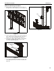
7. Install two 5/16-18 x 3/4" button head flange screws (BB)
into the top holes on each quick connect base (Q). (See
Figure 9)
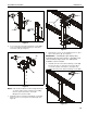
Figure 9
8. Hang rails (K or L) into screws installed in previous step to
quick connect bases (Q). (See Figure 9)
IMPORTANT ! : If installing the triple display rail (L),
install rail to left and center columns so that add-on rail
can be installed to right column. See Add-On Rail
Installation section for details.
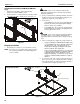
9. Install two 5/16-18 x 3/4" button head flange screws (BB)
into the lower holes on each quick connect base (Q) to
secure rails to quick connect bases. (See Figure 10)
10. Tighten all 5/16-18 x 3/4" button head flange screws (BB).
Figure 10
(AA)
(FF)
5
5
(CC) x 2
display
height
4
(Q)
(BB) x 4
6
(P)
(BB) x 2
8
8
7
(Q)
(K or L)
(BB) x 2
9