INSTALLATION INSTRUCTIONS Instrucciones de instalación Installationsanleitung Instruções de Instalação Istruzioni di installazione Installatie-instructies Instructions d´installation Height Adjustable Video Stand Spanish Product Description German Product Description Portuguese Product Description Italian Product Description Dutch Product Description French Product Description LFAU
LFAU Installation Instructions DISCLAIMER Milestone AV Technologies and its affiliated corporations and subsidiaries (collectively “Milestone”), intend to make this manual accurate and complete. However, Milestone makes no claim that the information contained herein covers all details, conditions or variations, nor does it provide for every possible contingency in connection with the installation or use of this product.
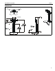
Installation Instructions LFAU DIMENSIONS +/-2 ROLL ADJUSTMENT TILT ADJUSTMENT 7.87 [200] MIN 31.50 [800] MAX 15.75 400.
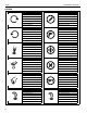
LFAU Installation Instructions LEGEND 4 Tighten Fastener Pencil Mark Apretar elemento de fijación Marcar con lápiz Befestigungsteil festziehen Stiftmarkierung Apertar fixador Marcar com lápis Serrare il fissaggio Segno a matita Bevestiging vastdraaien Potloodmerkteken Serrez les fixations Marquage au crayon Loosen Fastener Drill Hole Aflojar elemento de fijación Perforar Befestigungsteil lösen Bohrloch Desapertar fixador Fazer furo Allentare il fissaggio Praticare un foro Bevesti
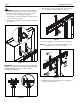
Installation Instructions LFAU TOOLS REQUIRED FOR INSTALLATION #2 M5 (included) 3/16” (included) PARTS M (1) [hardware bag] C (1) [column upper cover] A (4) [upright cover] B (2) [interface upright] D (1) [column inner cover] F (1) [column assembly] G (1) [back cover] E (1) [interface head assembly] MA (8) M4x16mm MB (6) M4x20mm MC (6) M4x25mm MD (6) M5x16mm ME (6) M5x20mm MF (6) M5x25mm MH (6) M6x25mm MG (6) M6x16mm H (2) [base plate] J (8) 5/16-18 x 1/2” K (5) 5/16-18 x 3/4” MI (6) M8
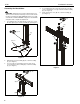
LFAU Installation Instructions Assembly And Installation CAUTION: Attachment holes may be damaged if a power 4. Use remaining 5/16-18 x 3/4” button head cap screw (K) to secure column upper cover (C) to interface head assembly (E). (See Figure 3) 5. Snap column inner cover (D) onto column assembly (F). (See Figure 3) drill is used to insert button head cap screws.
Installation Instructions LFAU Display Installation CAUTION: Using screws of improper length may damage your display! Proper screws will have adequate thread engagement without contacting bottom of display mounting holes. WARNING: Exceeding the weight capacity can result in serious personal injury or damage to equipment! It is the installer’s responsibility to make sure the combined weight of all components attached to the LFAU up to (and including) the display does not exceed 200 lbs (90.7 kg).
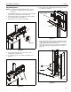
LFAU Installation Instructions 9. WARNING: Display may be very heavy! Ensure display Move latches on interface uprights to the “closed” position to secure display to head assembly. (See Figure 7) may be safely lifted and maneuvered as required to install on stand. Failure to take adequate precautions can result in serious personal injury or damage to equipment! 7. Position latches on interface uprights so that they are in the “open” position. (See Figure 5) 8.
Installation Instructions LFAU 6. Cable Management NOTE: The following cable management options may vary Route cables from display through front channel of column assembly. (See Figure 11) based on type of display being mounted and user preference. 1. Place FCA clip (N) into groove on back of Fusion mount with clip handle in a vertical position. (See Figure 9) 2. Rotate FCA clip (N) 90° in either direction until clip handle is in a horizontal position. (See Figure 9) 3.
LFAU Installation Instructions Adjustments Pitch Adjustment Height Adjustment 5. Turn pitch adjustment knob clockwise to tilt display forward. (See Figure 15) 6. Turn pitch adjustment knob counterclockwise to tilt display back. (See Figure 15) 1. Remove cable cover (G) to expose height adjustment knob. 2. Turn height adjustment knob clockwise to raise display. (See Figure 13) 3. Turn height adjustment knob counterclockwise to lower display.
Installation Instructions LFAU Stand Use and Maintenance open position WARNING: Exceeding the weight capacity can result in serious personal injury or damage to equipment! It is the installer’s responsibility to make sure the combined weight of all components located between the LFAU up to (and including) the display does not exceed 200 lbs (90.7 kg).
LFAU Installation Instructions USA/International Europe Chief, a products division of Milestone AV Technologies 8800-002511 Rev02 2014 Milestone AV Technologies www.chiefmfg.com 01/14 Asia Pacific A P F A P F A 6436 City West Parkway, Eden Prairie, MN 55344 800.582.6480 / 952.225.6000 877.894.6918 / 952.894.6918 Franklinstraat 14, 6003 DK Weert, Netherlands +31 (0) 495 580 852 +31 (0) 495 580 845 Office No.