INSTALLATION INSTRUCTIONS Instrucciones de instalación Installationsanleitung Instruções de Instalação Istruzioni di installazione Installatie-instructies Instructions d´installation LVM2X2U LVM3X2U LVM3X3U Video Wall Carts Spanish Product Description German Product Description Portuguese Product Description Italian Product Description Dutch Product Description French Product Description LVM Series
LVM Series Installation Instructions DISCLAIMER Milestone AV Technologies and its affiliated corporations and subsidiaries (collectively "Milestone"), intend to make this manual accurate and complete. However, Milestone makes no claim that the information contained herein covers all details, conditions or variations, nor does it provide for every possible contingency in connection with the installation or use of this product.
Installation Instructions LVM Series DIMENSIONS LVM2X2 MAX WEIGHT: 125 LBS PER DISPLAY 500 LBS TOTAL 72.00 1828.8 3.73 94.7 1.85 47.1 1.50 38.1 2.53 64.1 72.00 1828.8 SCREEN CENTER MAX HEIGHT 15.75 400.0 MAX MOUNTING PATTERN HEIGHT 74.54 1893.3 1.50 38.1 24.00 [609.6] SCREEN CENTER MIN HEIGHT 32.45 824.1 6.97 176.9 8.47 215.0 73.50 1866.9 5.38 136.5 3.77 95.8 25.47 646.8 4.25 108.0 45.56 1157.3 1.49 37.9 36.00 914.4 40.40 1026.2 6.97 176.
LVM Series Installation Instructions LVM3X3 100 LBS PER DISPLAY 900 LBS TOTAL 15.75 400.0 MAX MOUNTING PATTERN HEIGHT 108.00 2743.2 88.27 2242.1 3.73 94.7 90.00 2286.0 SCREEN CENTER MAX HEIGHT 24.00 [609.6] SCREEN CENTER MIN HEIGHT 6.97 176.9 8.47 215.0 4 92.54 2350.5 5.38 136.5 91.50 2324.1 3.77 95.8 1.50 38.1 38.48 977.4 2.53 64.1 25.47 646.8 42.44 1077.9 94.06 2389.2 4.25 108.0 6.97 176.9 1.49 36.00 37.9 914.4 40.40 1026.2 6.97 176.
Installation Instructions LVM Series LEGEND Tighten Fastener Pencil Mark Apretar elemento de fijación Marcar con lápiz Befestigungsteil festziehen Stiftmarkierung Apertar fixador Marcar com lápis Serrare il fissaggio Segno a matita Bevestiging vastdraaien Potloodmerkteken Serrez les fixations Marquage au crayon Loosen Fastener Drill Hole Aflojar elemento de fijación Perforar Befestigungsteil lösen Bohrloch Desapertar fixador Fazer furo Allentare il fissaggio Praticare un foro Beves
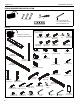
LVM Series Installation Instructions TOOLS REQUIRED FOR INSTALLATION #2 1/2" (12.7mm) 3/16" (included with all) 1/8" (included with 3x2,3x3) 5/32" (included with 3x3) PARTS Hardware bag (letters correspond to letters on bag) *Quantities are listed as (LVM2X2/LVM3X2/LVM3X3) G (16/24/36) M8x16mm F (16/24/36) M8x12mm J (1/2/2) [base cross bar] N (2/3/3) [column cap] K (2/0/0) [dual display rail] M (2/3/3) [cart array column] P (4/6/9) [clamp bracket] D (16/24/36) E (16/24/36) 1/4" .750x.344x.
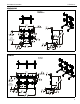
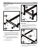
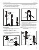
Installation Instructions LVM Series Assembly And Installation Cart Assembly LVM2X2 1. Lay two cart array columns (M) down on a flat surface. 2. Use eight 5/16-18 x 2 1/2" button head cap screws (EE) and eight 5/16" washers (JJ) to connect cross bar (J) to columns (M). (See Figure 1) 4 (GG) x 4 (CC) (DD) (JJ) x 4 3 (LL) x 4 (R) x 2 (M) x 2 4 (NN) x 4 (J) Figure 2 LVM3X2/LVM3X3 (JJ) x 8 2 1. Lay two cart array columns (M) down on a flat surface. 2.
LVM Series 5. Installation Instructions Place two extender blocks (U) in position between two extender brackets (W). Be sure to line up holes on blocks and brackets. (See Figure 4) (M) 5 (U) x 2 6 (EE) x 4 interior holes front (W) x 2 exterior holes Figure 4 6. back Figure 5 While holding extender blocks in position, install four 5/1618 x 2 1/2" button head cap screws (EE) through extender brackets (W), extender blocks (U) and into remaining cart array column (M). (See Figure 5) 7.
Installation Instructions LVM Series Column Add-On Installation (LVM3X3 only) 1. Insert one column add-on (V) to each of three columns (M) making sure holes are lined up on each side. (See Figure 7) 2. Use eighteen 1/4-20 x 1/2" flat head cap screws (X) to secure column add-ons (V) to columns (M). (See Figure 7) 3. Use 5/16-18 x 4 1/2" button head cap screw (FF), two 5/16" washers (JJ) and 5/16-18" lock nut (NN) to secure each clamp bracket (P) to column.
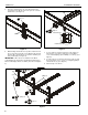
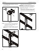
LVM Series 6. Installation Instructions Use four 5/16-18 x 3/4" button head flange screws (HH) to secure each attached clamp bracket (P) to a quick connect base (Q). (See Figure 11) 6 (Q) (HH) x 4 8. Hang rails (K or L) into screws installed in previous step to quick connect bases (Q). (See Figure 12) IMPORTANT ! : If installing the triple display rail (L), install rail to left and center columns so that add-on rail can be installed to right column. See Add-On Rail Installation section for details.
Installation Instructions LVM Series Add-On Rail Installation (LVM3X2/LVM3X3 only) 1. Install add-on rail (KK) to right column following instructions in Rails Installation section. 2. Use three #10-24 x 1 1/2" flat head cap screws (Z) to attach each add-on rail (KK) to display rail (L). (See Figure 14) 2 CAUTION: Using screws of improper diameter may damage your display! Proper screws will easily thread into display mounting holes. 2.
LVM Series Installation Instructions WARNING: Exceeding the weight capacity can result in serious personal injury or damage to equipment! It is the installer’s responsibility to make sure the combined weight of each display and attached accessories mounted to the LVM mount does not exceed 125 lbs (56.7 kg) per display or 500 lbs (226.8 kg) total for the LVM2X2, 125 lbs (56.7 kg) per display or 750 lbs (340.2 kg) total for the LVM3X2 or 100 lbs (45.4 kg) per display or 900 lbs (408.
Installation Instructions LVM Series Column Cap Installation Cable Management NOTE: If the top holes on columns will be used for cable 1. management, do NOT install column caps to columns as illustrated below. See Cable Management section for details. 1. Route cables from displays through nearest holes on front of columns and out through back cable management hole. (See Figure 21) NOTE: For best access, route display cables through columns prior to display installation.
LVM Series Installation Instructions 3. If rails needed to be installed on top of cable management holes, cables may be routed through quick connect bases (Q) prior to the rails being installed. (See Figure 23) 4. Install rails according to Rails Installation section making sure cable is routed through cable opening on quick connect base (Q). (See Figure 23) cable from uninstalled display 4 3 Figure 23 5.
Installation Instructions LVM Series 15
LVM Series Installation Instructions USA/International Europe Chief Manufacturing, a products division of Milestone AV Technologies 8800-002168 Rev02 2012 Milestone AV Technologies, a Duchossois Group Company www.chiefmfg.com 06/12 Asia Pacific A P F A P F A 6436 City West Parkway, Eden Prairie, MN 55344 800.582.6480 / 952.225.6000 877.894.6918 / 952.894.6918 Franklinstraat 14, 6003 DK Weert, Netherlands +31 (0) 495 580 852 +31 (0) 495 580 845 Office No.