INSTALLATION INSTRUCTIONS Single and Dual Display Floor Stands MF1, MF2, PF1, PF2 Series
MF1, MF2, PF1, PF2 Series Installation Instructions DISCLAIMER Milestone AV Technologies, and its affiliated corporations and subsidiaries (collectively, "Milestone"), intend to make this manual accurate and complete. However, Milestone makes no claim that the information contained herein covers all details, conditions or variations, nor does it provide for every possible contingency in connection with the installation or use of this product.
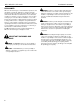
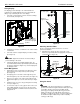
Installation Instructions MF1, MF2, PF1, PF2 Series DIMENSIONS MF1, MF2 PF1, PF2 3
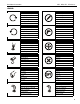
Installation Instructions MF1, MF2, PF1, PF2 Series LEGEND Tighten Fastener Pencil Mark Apretar elemento de fijación Marcar con lápiz Befestigungsteil festziehen Stiftmarkierung Apertar fixador Marcar com lápis Serrare il fissaggio Segno a matita Bevestiging vastdraaien Potloodmerkteken Serrez les fixations Marquage au crayon Loosen Fastener Drill Hole Aflojar elemento de fijación Perforar Befestigungsteil lösen Bohrloch Desapertar fixador Fazer furo Allentare il fissaggio Praticare
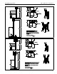
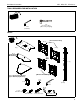
Installation Instructions MF1, MF2, PF1, PF2 Series TOOLS REQUIRED FOR INSTALLATION 3/16" (included) 1/4" (To remove base plates from packaging) PARTS [PF Head Assemblies] D (1) D1 (1) A (1) B (1) (Single Display Models Only) OR F (1) E (1) C [(2) for Single Display Models] [(4) for Dual Display Models] G (4) [MF Head Assemblies] E1 (1) H (1) 3/16" J (1) 3/16" (Front) Q (4) 5/16" L (12) 5/16-18 x 1/2" M (4) 5/16-18 x 3/4" N (4) 5/16-18 x 1-1/2" P (1) K (1) 1/4-20 x 3/8" 1/4" (Dual Displ
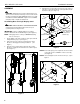
MF1, MF2, PF1, PF2 Series Installation Instructions ASSEMBLY 4. Attach top base section (A) to the center post (F) using four 5/16-18 x 1-1/2" button head cap screws (N) and four 5/16" flat washers (Q). (See Figure 2) CAUTION: Attachment holes may be damaged if a power drill is used to insert button head cap screws. Screws should first be inserted and turned BY HAND with the hex key or with a handheld screwdriver BEFORE using the hex head drill bit and power drill to complete the attachment.
Installation Instructions 5. MF1, MF2, PF1, PF2 Series Gather stand base pieces B and C (2) as shown in Figure 4 and push them together until the edges meet. IMPORTANT ! : Press cable tie tab to loosen and remove cable tie from around knob post. (See Figure ) NOTE: Disengage knob on center post BEFORE attaching base to center post. (B) 1. Follow Steps 1-4 (and Figures 1, 2 and 3) of Assembling Base for Single Display Stand. 2.
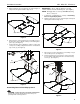
MF1, MF2, PF1, PF2 Series Installation Instructions Attaching Single Head Assembly IMPORTANT ! : When attaching head assembly ensure that the ClickConnect lock is at TOP of head assembly, and bracket tabs slide into the stand assembly. (See Figure 8) 1. Slide head assembly (D) or (E) into the stand assembly. (See Figure 8) 2. Attach head assembly to stand using four 5/16-18 x 3/4" button head cap screws (M).
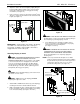
Installation Instructions 2. 3. MF1, MF2, PF1, PF2 Series Adjust the stand to the desired height by slightly lifting the head assembly, pulling out knob on the center post and turning 90o in either direction to disengage the locking mechanism. (See Figure 11) 2 Raise or lower the center post, then turn the knob 90o either direction to engage the knob and lock the stand at desired height.
MF1, MF2, PF1, PF2 Series Installation Instructions Tilting Display The display(s) can be tilted up to 15o either backward or forward from a straight upright position. In a dual stand, the tilting is only restricted by the size of the display. 1. (Front view of center post) 1 Turn knob counterclockwise on back of head assembly to loosen the tilt.
Installation Instructions WARNING: STAND CAN TIP OVER RESULTING IN RISK OF INJURY. Never move the stand when displays are attached. Never push against the stand. MF1, MF2, PF1, PF2 Series 1 Remove bolt or padlock if used 2 Removing Display(s) from Stand 1. Remove bolt or padlock from faceplate (if used). NOTE: The pin may have been used as a more permanent locking device. If so, remove nut and pin and move from the lower holes to the upper holes. 2.
MF1, MF2, PF1, PF2 Series Installation Instructions USA/International Europe Chief Manufacturing, a products division of Milestone AV Technologies 8809-000039 RevG 2009 Milestone AV Technologies, a Duchossois Group Company www.chiefmfg.com 12/09 Asia Pacific A P F A P F A 8401 Eagle Creek Parkway, Savage, MN 55378 800.582.6480 / 952.894.6280 877.894.6918 / 952.894.6918 Fellenoord 130 5611 ZB EINDHOVEN, The Netherlands +31 (0)40 2668620 +31 (0)40 2668615 Office No.