
User's Manual


Installation Instructions FSB4090
5
ASSEMBLY AND INSTALLATION
NOTE: The following procedure assumes that a Chief K2
Series swing arm mount (not included) has already
been installed following instructions included with the
mount.
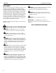
1. Hook two clips (C) over top of display, with long edge of clip
on back of display. (See Figure 1)
Figure 1
2. Slide interface bracket (A) up from bottom along back of
display, ensuring that bottom of interface bracket hooks the
extension bracket on back of display. (See Figure 2)
3. Hang interface bracket onto studs at bottom of clips (C).
(See Figure 2)
Figure 2
4. Fasten interface bracket to clips using four #10-24 locknuts
(F). (See Figure 2)
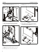
5. Attach two M4 locknuts (E) and two M4 washers (G) to top
two studs on back of interface bracket (A). Thread nuts
completely onto studs and then back out three complete
turns. (See Figure 3)
Figure 3
6. Lower interface bracket and display onto K2 Series mount
faceplate by setting top two studs into top two mounting
holes on faceplate. (See Figure 4)
7. Install two M4 locknuts (E) and two M4 washers (G) onto
lower two studs on back of display. (See Figure 4)
8. Tighten all four locknuts (E). (See Figure 4)
Figure 4
1
(C)
1
Back of
display
4
(F) x 4
2
(A)
(C)
Hooks on
extension
bracket
Extension
bracket
(E) x 2
5
(G) x 2
7
(E) x 2
6
(G) x 2