INSTALLATION INSTRUCTIONS Instrucciones de instalación Installationsanleitung Instruções de Instalação Istruzioni di installazione Installatie-instructies Instructions d´installation WM-210SI WM-220SI WM-230SI WM-240SI Dual Stud Short Throw Wall Mounts Spanish Product Description German Product Description Portuguese Product Description Italian Product Description Dutch Product Description French Product Description WM210-220-230-240S/SI
WM210-220-230-240S/SI Installation Instructions DISCLAIMER Milestone AV Technologies and its affiliated corporations and subsidiaries (collectively "Milestone"), intend to make this manual accurate and complete. However, Milestone makes no claim that the information contained herein covers all details, conditions or variations, nor does it provide for every possible contingency in connection with the installation or use of this product.
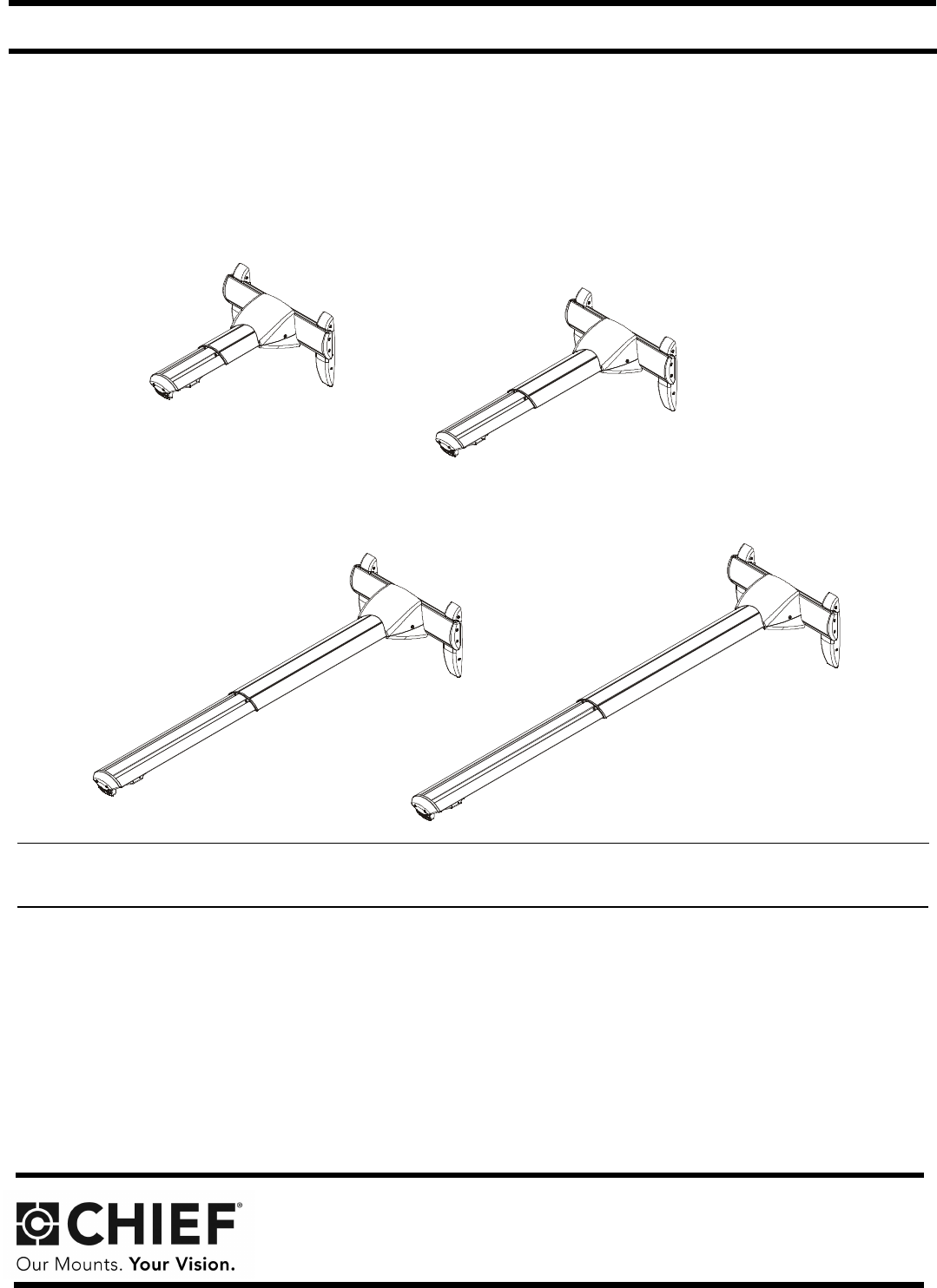
Installation Instructions WM210-220-230-240S/SI DIMENSIONS WM2XXS (Standard Model) 240S, TRAVEL 37.2" - 65.6" .75 210S, TRAVEL 12.75" - 19.5" 16.00 .34 3.96 7.25 7.25 10.81 3 OF 11.53 5.64 5.36 19.63 1.42 1.09 CABLE CHANNEL DIMENSIONS THRU ARM DIMENSIONS: INCHES WM2XXSI (Interactive Model) 240SI, TRAVEL 37.2" - 65.6" 19.06 .75 210SI, TRAVEL 12.75" - 19.5" 102.87 4.05 3 OF 406.40 16.00 184.14 7.25 274.64 10.81 8.69 .34 292.85 11.53 148.43 5.84 5.36 498.53 19.63 36.12 1.42 27.62 1.
WM210-220-230-240S/SI Installation Instructions LEGEND 4 Tighten Fastener Pencil Mark Apretar elemento de fijación Marcar con lápiz Befestigungsteil festziehen Stiftmarkierung Apertar fixador Marcar com lápis Serrare il fissaggio Segno a matita Bevestiging vastdraaien Potloodmerkteken Serrez les fixations Marquage au crayon Loosen Fastener Drill Hole Aflojar elemento de fijación Perforar Befestigungsteil lösen Bohrloch Desapertar fixador Fazer furo Allentare il fissaggio Praticare
Installation Instructions WM210-220-230-240S/SI TOOLS REQUIRED FOR INSTALLATION 5/32" (included) (security) 3/16" (included) 1/2" (12.7mm) 1/2" (12.7mm) 3/8" (9.5mm) 7/32" (5.
WM210-220-230-240S/SI Installation Instructions SITE REQUIREMENTS (WM2XXSI and WM2XXS Models) - Steel Stud Structure WARNING: IMPROPER INSTALLATION CAN LEAD TO EQUIPMENT FALLING CAUSING SERIOUS PERSONAL INJURY OR DAMAGE TO EQUIPMENT! The figure below identifies the minimum requirements for installation of display mounts onto a steel stud structure. If the structure or its components do not meet these requirements contact the mount manufacturer for specific instructions before attempting installation.
WM210-220-230-240S/SI Installation Instructions Connection Requirement WS2XXSI INTERACTIVE MODEL ONLY The Chief Interactive Mount (WM2XXSI) works with standard projectors and Windows® and Macintosh® computers. The Interactive Mount will transform existing whiteboards or other hard, flat surfaces, into interactive whiteboards and allows users to present, annotate, and interact with their projected content and all of their desktop applications.
Installation Instructions WM210-220-230-240S/SI WM2XXSI Placement and Projection Area Constraints (See Figure 3) • • • • There should be a minimum distance of 12 inches between the base of the dual mount and the top of the projection image. The distance between the base of the dual mount and the bottom corner of the projection image (both right and left) should be less than or equal to 110 inches. The projection image should start a minimum of 1 inch from the base of the top frame of the whiteboard.
Installation Instructions WM210-220-230-240S/SI ASSEMBLY AND INSTALLATION - (WM2XXSI and WM2XXS MODELS) 5 The WM-210S/SI, -220S/SI, -230S/SI and -240S/SI short throw projector mounts can be mounted to concrete, concrete block, wood studs or steel studs. They can be mounted to 2" x 4" wood studs up to 16" apart. For studs more than 16" apart, the WMAL24 accessory (not evaluated and tested by Underwriters Laboratories®) can be used to mount projector.
WM210-220-230-240S/SI 5. Installation Instructions Install four 5/16 x 2-1/2" hex head lag screws (L) through four 5/16" washers (M), holes of wall bracket and into drilled holes. (See Figure 7) 5. Hold metal channel on anchor (P) flat alongside plastic straps and slide channel through hole. (See Figure 9) Drywall 5 (L) x 4 Plastic straps 5 (M) x 4 (P) x 4 (B) Figure 9 6. 7.
Installation Instructions WM210-220-230-240S/SI 10. Place wall bracket over anchors and align mounting holes in display mount with holes in anchors. (See Figure 12) 2. Slide lower plate onto cross bracket on mounting bracket. (See Figure 14) 11. Insert 1/4-20 x 1-3/4" Phillips pan head screws (N) through 1/4" washer (Q), corresponding mounting hole on wall bracket and into anchor (P) and tighten until flush against mount. DO NOT overtighten! (See Figure 12) (B) 12.
WM210-220-230-240S/SI Installation Instructions 4. Loosen two bolts on either side of pitch adjustment screw. (See Figure 16) NOTE: Determine hole configuration to use for each specific 5. Adjust pitch adjustment screw until mount is at desired pitch level. Turn clockwise to raise mounting level or turn counterclockwise to lower mounting level. (See Figure 16) RPM Installation 6. Tighten two bolts on either side of pitch adjustment screw. (See Figure 16) raise 5 projector mount.
Installation Instructions WM210-220-230-240S/SI RPA Installation 1. Line up mounting holes on RPA mount with corresponding holes on projector mounting plate. (See Figure 17) 2. Install four 1/4-20 x 3/8" Phillips pan machine screws (G) through RPA holes and into projector mounting plate. (See Figure 20) IMPORTANT ! : Complete the installation by proceeding to WM2XXSI Interactive Mount section or WM2XXS Standard Mount section, as appropriate. WM2XXSI INTERACTIVE MOUNT Installing Mount Covers 1.
WM210-220-230-240S/SI 4. Installation Instructions Lower the upper cover (X) onto the wall mount and lower cover, and fasten with two 8-32 x 3/8" Phillips pan head screws (AB). (See Figure 24) 3. Remove and save two 8-32 x 3/8" Phillips pan head screws (AB) from lower cover. (See Figure 26) NOTE: Be sure cables and cords are not pinched between upper and lower covers. (AB) x 2 3 (X) 4 Lower cover (AB) x 2 4 Figure 24 Cable Management (Optional) Figure 26 4.
Installation Instructions WM210-220-230-240S/SI NOTE: Cables may be routed from below and up wall bracket channel, or from above and down behind and into wall mount. • 6. (view from front) Cables Routing Cables from Below (Steps 6 and 7) 8 Open cable clips along bottom edge of wall bracket. (See Figure 28) 6 Surface Mount Cable Accessory (not included) Cables cable clips x4 Figure 28 7. 8 Thread cable up wall bracket channel and into opened cable clips.
WM210-220-230-240S/SI 10. (Optional) Cables can be tied to inside of mount’s front cover using cable ties (not included). Route cables near front cover and wrap cable tie through slots on front cover and around cables. (See Figure 32) Installation Instructions Installation of Wall Bracket Covers NOTE: If security screws are going to be used, use the security screws (V) to install wall bracket covers. See Security Screw Installation section for details. 1.
Installation Instructions WM210-220-230-240S/SI Adjustments 2. Loosen two bolts on either side of pitch adjustment screw. (See Figure 38) Bracket Width Adjustment 3. Adjust pitch adjustment screw until mount is at desired pitch level. Turn clockwise to raise mounting level or turn counterclockwise to lower mounting level. (See Figure 38) 1. Loosen two flat head cap screws on wall bracket. (See Figure 36) 2. Slide wall brackets to corresponding width of studs. (See Figure 36) 4.
WM210-220-230-240S/SI Installation Instructions 2. Lateral Shift Adjustment IMPORTANT ! : The mount covers need to be removed before proceeding with lateral shift adjustment. NOTE: Remove mount covers from the mount following 2 instructions in Removing Mount Covers section. 1. Loosen two 1/4-20 x 5/8" hex head cap screws (E) on underside of mounting bracket. (See Figure 40) 2. Adjust projector arm laterally to desired position. (See Figure 40) 3.
Installation Instructions 3. WM210-220-230-240S/SI Remove two 8-32 x 3/8" Phillips pan head screws (AB) from lower cover. (See Figure 44) 7 3 (AB) x 2 Figure 46 Lower cover Stop Bracket 1. Figure 44 4. (AA) x 2 Remove two bolts holding stop bracket in place on underside of short throw projector mount. (See Figure 47) Install two 8-32 x 3/8" button head security screws (AA) into lower cover. (See Figure 45) 6 Stop bracket (AA) x 2 1 x2 Figure 47 Figure 45 5.
WM210-220-230-240S/SI 2. Installation Instructions Install two 1/4-20 x 1/2" button head security screws (T) through holes in stop bracket and into holes in sliding nuts. (See Figure 48) Adapter plate Sliding nuts locations Stop bracket 2 (T) x 2 x 4 (one at a time) 2 Figure 48 Adapter Plate Bolts 1. Remove projector from short throw projector mount according to projector interface instructions. NOTE: For most projectors, it will be necessary to remove Figure 49 3.
Installation Instructions WM210-220-230-240S/SI WM2XXS STANDARD MOUNT Cable Management (Optional) Installing Mount Covers In most cases, cable management covers will NOT need to be removed in order to route cables from projector to the wall mount. But for some thick cables, removing the covers may be necessary. 1. Raise the lower cover (AK) to wall mount and hold in place. (See Figure 51) Removing Mount Covers 1. Remove and save two 8-32 x 1/2" Phillips pan head screws from upper cover.
WM210-220-230-240S/SI 4. Installation Instructions Remove cable management covers (if necessary) from short throw projector arm. (See Figure 55) (bottom view) Cables (example) 4 4 Cable management covers Figure 57 • 7. Figure 55 Routing Cables from Above (Step 7) Thread cables down through a surface mount cable accessory (not included), then behind and into the wall bracket.
Installation Instructions 8. WM210-220-230-240S/SI Route cables through cover mount, projector arm tunnel and into projector. (See Figure 59) Cables (example) 10 Figure 61 Cable clips 11. Return outer covers to the mount following instructions in Installing Mount Covers section. Installation of Wall Bracket Covers NOTE: If security screws are going to be used, use the security screws (V) to install wall bracket covers. See Security Screw Installation section for details. Figure 59 9.
WM210-220-230-240S/SI 4. Installation Instructions Secure wall bracket bottom caps (D) to wall bracket arms by installing four #8-32 x 1/2" Phillips pan machine screws (F) through holes in covers and wall bracket. (See Figure 63) 1. Loosen two 1/4-20 x 5/8" hex head cap screws (E) on underside of mounting bracket. (See Figure 65) (F) x 4 2 1 4 5 (E) x 2 (F) x 4 (bottom view) (Projector arm not shown for display purposes) Figure 65 Figure 63 Adjustments 2.
Installation Instructions WM210-220-230-240S/SI Security Screw Installation (Optional) (bottom view) Wall Bracket Covers 1. 2 Remove eight #8-32 x 1/2" Phillips pan machine screws (F) from wall bracket covers. (See Figure 69) 1 (F) x 8 3 1 Figure 67 Lateral Shift Adjustment IMPORTANT ! : The mount covers need to be removed before proceeding with lateral shift adjustment.
WM210-220-230-240S/SI Installation Instructions Mount Covers 1. Remove two #8-32 x 1/2" Phillips pan machine screws (F) holding mount covers on projector arm. (See Figure 71) 2. Install two #8-32 x 1/2" button head security screws (V) into holes on mount cover. (See Figure 71) Stop bracket 1 (F) x 2 1 x2 Figure 72 2. Install two 1/4-20 x 1/2" button head security screws (T) through holes in stop bracket and into holes in sliding nuts.
Installation Instructions WM210-220-230-240S/SI Adapter Plate Bolts 1. Remove projector from short throw projector mount according to projector interface instructions. NOTE: For most projectors, it will be necessary to remove projector prior to installing four security screws to projector bracket. For ease of installation, it is recommended to remove projector prior to performing the following steps.
WM210-220-230-240S/SI Installation Instructions USA/International Europe Chief Manufacturing, a products division of Milestone AV Technologies 8802-002082 Rev03 2011 Milestone AV Technologies, a Duchossois Group Company www.chiefmfg.com 12/11 Asia Pacific A P F A P F A 8401 Eagle Creek Parkway, Savage, MN 55378 800.582.6480 / 952.894.6280 877.894.6918 / 952.894.6918 Franklinstraat 14, 6003 DK Weert, Netherlands +31 (0) 495 580 852 +31 (0) 495 580 845 Office No.