INSTALLATION INSTRUCTIONS Dual Stud Wall Mount Accessory Spanish Product Description German Product Description Portuguese Product Description Italian Product Description Dutch Product Description French Product Description WMA2S
WMA2S Installation Instructions DISCLAIMER Milestone AV Technologies and its affiliated corporations and subsidiaries (collectively "Milestone"), intend to make this manual accurate and complete. However, Milestone makes no claim that the information contained herein covers all details, conditions or variations, nor does it provide for every possible contingency in connection with the installation or use of this product.
Installation Instructions WMA2S LEGEND Tighten Fastener Pencil Mark Apretar elemento de fijación Marcar con lápiz Befestigungsteil festziehen Stiftmarkierung Apertar fixador Marcar com lápis Serrare il fissaggio Segno a matita Bevestiging vastdraaien Potloodmerkteken Serrez les fixations Marquage au crayon Loosen Fastener Drill Hole Aflojar elemento de fijación Perforar Befestigungsteil lösen Bohrloch Desapertar fixador Fazer furo Allentare il fissaggio Praticare un foro Bevestigin
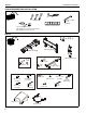
WMA2S Installation Instructions TOOLS REQUIRED FOR INSTALLATION #2 5/32" (security) 3/16" (included) 1/2" (12.7mm) 1/2" (12.7mm) steel stud 3/8" (10mm) concrete and concrete block 7/32" (5.
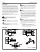
Installation Instructions WMA2S Site Requirements WARNING: IMPROPER INSTALLATION CAN LEAD TO EQUIPMENT FALLING CAUSING SERIOUS PERSONAL INJURY OR DAMAGE TO EQUIPMENT! The figure below identifies the minimum requirements for installation of display mounts onto a steel stud structure. If the structure or its components do not meet these requirements contact the mount manufacturer for specific instructions before attempting installation.
WMA2S Installation Instructions ASSEMBLY AND INSTALLATION The WMA2S dual stud wall mount accessory can be mounted to concrete, concrete block, 2" x 4" wood studs (16" on center) or steel studs. It can be mounted to studs up to 16" apart.
Installation Instructions 5. WMA2S Install four 5/16 x 2-1/2" hex head lag screws (E) through four 5/16" washers (F), holes of mounting bracket and into drilled holes. (See Figure 4) 5. Hold metal channel on anchor (J) flat alongside plastic straps and slide channel through hole. (See Figure 6) Drywall 5 (E) x 4 Plastic Straps 5 (F) x 4 (J) x 4 Figure 6 6. (B) 7.
WMA2S Installation Instructions 10. Place wall bracket over anchors and align mounting holes in mounting bracket with holes in anchors. (See Figure 9) 2. Slide lower plate onto cross bracket on mounting bracket. (See Figure 11) 11. Insert 1/4-20 x 1-3/4" Phillips pan head screws (H) through 1/4" washer (G), corresponding mounting hole on mounting bracket (B) and into anchor (J) and tighten until flush against mount. DO NOT overtighten! (See Figure 9) (B) 12.
Installation Instructions WMA2S 4. Loosen two bolts on either side of pitch adjustment screw. (See Figure 13) 5. Adjust pitch adjustment screw until mount is at desired pitch level. • • 6. 2. Lower the upper cover (V) onto the wall mount and fasten through upper cover (V), lower cover (W) and into wall mount with two 8-32 x 1/2" Phillips pan head screws (T). (See Figure 15) Turn clockwise to raise mounting level. Turn counterclockwise to lower mounting level.
WMA2S Installation Instructions PROJECTOR INSTALLATION WARNING: Exceeding the weight capacity can result in serious personal injury or damage to equipment! It is the installer’s responsibility to make sure the combined weight attached to the wall mount accessory up to (and including) the attached component(s) does not exceed: • • • 2 Installed in steel stud: 75 lbs (34.0 kg) Installed in 2" x 4" wood stud: 150 lbs (68.
Installation Instructions 4. WMA2S Remove cable management cover (if necessary) from WMA2S arm. (See Figure 19) (bottom view) 4 Cables (example) Wall bracket channels Cable management cover Figure 21 • Figure 19 NOTE: Cables may be routed from below and up wall bracket 7. Routing Cables from Above (Step 7) Thread cables down through a surface mount cable accessory (not included), then behind and into the wall bracket.
WMA2S 8. Installation Instructions Route cables through cover mount, WMA2S arm and into column. (See Figure 23) 10. Replace removed cable management cover (if necessary) by snapping it into place. (See Figure 25) (bottom view) 10 Cable management cover 8 11. Replace mount covers on the mount following instructions in Installing Mount Covers section. 8 Installation of Mounting Bracket Covers Figure 23 9.
Installation Instructions 2. WMA2S Secure wall bracket top covers (C) to wall bracket arms by installing four #8-32 x 1/2" Phillips pan machine screws (T) through holes in covers and wall bracket. (See Figure 27) 3. Place wall bracket bottom covers (D) over bottom of each wall bracket arm. (See Figure 26) 4. Secure wall bracket bottom covers (D) to wall bracket arms by installing four #8-32 x 1/2" Phillips pan machine screws (T) through holes in covers and wall bracket.
WMA2S 7. Installation Instructions Install mount covers to the mount following instructions in Installing Mount Covers section. (bottom view) Extension Adjustment 1. Loosen two bolts holding stop bracket in place on underside of WMA2S mount. (See Figure 31) 2. Adjust mount to desired extension length. (See Figure 31) 3. Tighten two bolts holding stop bracket to secure mount in desired position. (See Figure 31) 1 3 3 3 2 4 (P) x 2 Figure 32 2 5.
Installation Instructions 2. WMA2S Install eight #8-32 x 1/2" button head security screws (M) into holes in wall bracket covers. (See Figure 34) Stop bracket 2 (M) x 8 5 x2 Figure 36 (Mount accessory arm not shown for clarity) 6. Figure 34 3. Remove two #8-32 x 1/2" Phillips pan machine screws (T) holding mount covers on WMA2S arm. (See Figure 35) 4. Install two #8-32 x 1/2" button head security screws (M) into holes on mount covers.
WMA2S Installation Instructions 8. Remove one of four bolts from adapter plate. (See Figure 38) 9. Install one 1/4-20 x 3/4" button head security screw (L) into hole vacated by removing bolt in Step 8 and into plastic spacer. (See Figure 39) 10. Repeat Steps 8-9 for remaining three bolts, one bolt at a time.
Installation Instructions WMA2S 17
WMA2S 18 Installation Instructions
Installation Instructions WMA2S 19
WMA2S Installation Instructions USA/International Europe Chief Manufacturing, a products division of Milestone AV Technologies 8802-002084 Rev00 2011 Milestone AV Technologies, a Duchossois Group Company www.chiefmfg.com 06/11 Asia Pacific A P F A P F A 8401 Eagle Creek Parkway, Savage, MN 55378 800.582.6480 / 952.894.6280 877.894.6918 / 952.894.6918 Fellenoord 130 5611 ZB EINDHOVEN, The Netherlands +31 (0)40 2668620 +31 (0)40 2668615 Office No.