INSTALLATION INSTRUCTIONS Instrucciones de instalación Installationsanleitung Instruções de Instalação Istruzioni di installazione Installatie-instructies Instructions d´installation WP2XS WP2XUS Short Throw Projector Wall Mounts Spanish Product Description German Product Description Portuguese Product Description Italian Product Description Dutch Product Description French Product Description WP2XS, WP2XUS
WP2XS, WP2XUS Installation Instructions DISCLAIMER Milestone AV Technologies and its affiliated corporations and subsidiaries (collectively "Milestone"), intend to make this manual accurate and complete. However, Milestone makes no claim that the information contained herein covers all details, conditions or variations, nor does it provide for every possible contingency in connection with the installation or use of this product.
Installation Instructions WP2XS, WP2XUS DIMENSIONS WP21S/US WP22S/US DIMENSION A 24.36 [618.8] 40.36 [1025.2] DIMENSION B MIN DIMENSION B MAX WEIGHT CAPACITY 3.62 [92.0] 22.12 [561.9] 25 LBS WP21S/US 8.62 219.0 1.00 25.
WP2XS, WP2XUS Installation Instructions LEGEND 4 Tighten Fastener Pencil Mark Apretar elemento de fijación Marcar con lápiz Befestigungsteil festziehen Stiftmarkierung Apertar fixador Marcar com lápis Serrare il fissaggio Segno a matita Bevestiging vastdraaien Potloodmerkteken Serrez les fixations Marquage au crayon Loosen Fastener Drill Hole Aflojar elemento de fijación Perforar Befestigungsteil lösen Bohrloch Desapertar fixador Fazer furo Allentare il fissaggio Praticare un foro
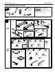
Installation Instructions WP2XS, WP2XUS TOOLS REQUIRED FOR INSTALLATION 5/32" 5/32" (security) (included) 1/4" (included) Hardware required, not included: Steel Stud Install 4 - Toggler® 1/4-20 (BB) Snap-Toggle 4 - Grade 2 or better 1/4-20 x 1-3/4" Phillips pan head screws 4 - Grade 2 or better 1/4" washer 1/2" 3/8" PARTS A (1) [Projector arm] B (1) [Wall plate cover - left] OR C (1) [Wall plate cover - right] (WP21S shown) ALL MODELS D (1) [End cap] (WP21US shown) J (8) M5 x 12mm H (1) M5 x 35
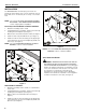
WP2XS, WP2XUS Installation Instructions INSTALLATION The WP2XS/WP2XUS short throw projector mounts are designed to be mounted to an 8" concrete, 8"x8"x16" concrete block, brick, 2" x 4" wood studs (16" on center), or steel studs wall. 2 x4 NOTE: Proceed to the Concrete, Concrete Block or Brick, 3 Wood Studs or Steel Studs Installation Installation section, as appropriate for installation. (F) Concrete, Concrete Block or Brick Installation 1. Determine mounting location on wall. 2.
Installation Instructions WP2XS, WP2XUS Site Requirements 16" (on center) Studs Short Throw Mount Installation Location (Must be centered over two studs) If back side of wall is unfinished, drywall must be installed to a minimum of one stud left and right of the studs being used to install the mount.
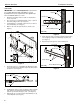
WP2XS, WP2XUS Installation Instructions Steel Studs Steel Stud IMPORTANT ! : See Site Requirements section before proceeding with Steel Studs installation to ensure installation site meets requirements! The drywall must have a minimum thickness of 1/2"! 1. Determine mounting location on wall. Use stud finder to locate steel studs. 2. Line up four holes on wall plate (E) with center of studs at desired mounting location. (See Figure 4) 3.
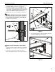
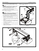
Installation Instructions WP2XS, WP2XUS 10. Place wall plate (E) over anchors and align mounting holes in wall plate with holes in anchors. (See Figure 8) 11. Insert Grade 2 or better 1/4-20 x 1-3/4" Phillips pan head screws (not included) through Grade 2 or better 1/4" washer (not included), corresponding mounting hole on wall bracket and into Snap-Toggle (not included) and tighten until flush against mount. DO NOT overtighten! (See Figure 8) 12. Repeat Steps 10 and 11 for remaining 3 mounting holes.
WP2XS, WP2XUS Installation Instructions NOTE: Proceed to Adjustments section to continue Projector Installation (WP2XUS Models Only) installation. WARNING: Exceeding the weight capacity can result in serious personal injury or damage to equipment! It is the installer’s responsibility to make sure the weight of the projector does not exceed 25 lbs (11.3 kg). 1. (A) Assemble and attach SSBU (W, X and Y) to projector following instructions included with SSBU.
Installation Instructions WP2XS, WP2XUS 7. Projector Installation (WP2XS Models Only) Tighten the M5x35mm button head cap screw (H) on the wall plate (E). (See Figure 14) WARNING: Exceeding the weight capacity can result in serious personal injury or damage to equipment! It is the installer’s responsibility to make sure the weight of the projector does not exceed 25 lbs (11.3 kg). 1. 2.
WP2XS, WP2XUS Installation Instructions Adjustments Projector Arm Height Adjustment Distance from Wall / Screen Size (See Figure 15) 13. Loosen two Phillips screws (one on left, one on right) on sides of projector arm plate. (See Figure 16) 1. Loosen two Phillips screws (one on left, one on right). 2. Slide the RSA mount along the projector arm (A), as required. 3. Tighten two Phillips screws. Yaw Adjustment (See Figure 15) 4. Loosen yaw adjustment screw using a 5/32" hex key. 14.
Installation Instructions WP2XS, WP2XUS Add Covers 1. Add left and right wall plate covers (B and C) over wall plate (E). (See Figure 18) 2. Fasten covers using four M5 x 12mm Phillips cap head screws (J). (See Figure 18) (J) x 2 2 1 (E) (C) (B) 1 (J) x 2 2 Figure 18 3. Add end cap (D) to end of short throw projector arm (A).
WP2XS, WP2XUS 14 Installation Instructions
Installation Instructions WP2XS, WP2XUS 15
WP2XS, WP2XUS Installation Instructions USA/International Europe Chief Manufacturing, a products division of Milestone AV Technologies 8800-002102 Rev02 2012 Milestone AV Technologies, a Duchossois Group Company www.chiefmfg.com 04/12 Asia Pacific A P F A P F A 6436 City West Parkway, Eden Prairie, MN 55344 800.582.6480 / 952.225.6000 877.894.6918 / 952.894.6918 Franklinstraat 14, 6003 DK Weert, Netherlands +31 (0) 495 580 852 +31 (0) 495 580 845 Office No.