INSTALLATION INSTRUCTIONS Furniture Racks Spanish Product Description German Product Description Portuguese Product Description Italian Product Description Dutch Product Description French Product Description YF1F12-20-28
YF1F12-20-28 Installation Instructions DISCLAIMER Milestone AV Technologies and its affiliated corporations and subsidiaries (collectively "Milestone"), intend to make this manual accurate and complete. However, Milestone makes no claim that the information contained herein covers all details, conditions or variations, nor does it provide for every possible contingency in connection with the installation or use of this product.
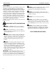
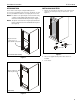
Installation Instructions YF1F12-20-28 DIMENSIONS MODEL WEIGHT CAPACITY LBS (KG) HEIGHT UNITS YF1F1228B YF1F2028H 300 (136) 300 (136) 500 (227) 12 12 20 OVERALL 34 (863.6) A B 30 (762) 30 (762) 30 (762) 24.12 (612.6) 26.63 (676.4) 24.12 (612.6) 26.63 (676.4) 34 (863.6) 34 (863.
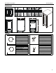
YF1F12-20-28 Installation Instructions TOOLS REQUIRED FOR INSTALLATION #2 7/16" PARTS A (1) [F1 rack] B (4) [Caster] (YF1F2828 shown) 4 C (4) [Caster spacer]
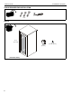
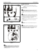
Installation Instructions YF1F12-20-28 INTRODUCTION INSTALLING CASTERS The F1 Series racks may be configured with optional accessories (not included) such as levelers, fan panels, etc. All accessory installation instructions accompany the accessories. 1. Attach one caster (B) to each lower corner of the F1 rack using one F1 caster spacer (C) for each caster. (See Figure 3) NOTE: The bottom cover panel may be removed for wire entry or may be replaced with a filtered fan panel.
YF1F12-20-28 Installation Instructions OPTIONAL ASSEMBLY Hinge Adjustment Levelers If necessary, the door hinges may be used to adjust the depth, horizontal or vertical placement of the doors (See Figure 5). 1. Add optional levelers to the rack following instructions included with the levelers. Doors (Change hinged side) NOTE: The doors can be changed to open on the opposite side from the way they shipped. 1. 1. Adjusting these screws will allow vertical adjustment (up and down) of the door.
Installation Instructions YF1F12-20-28 LOADING THE RACK (front view of rack) NOTE: The alignment panels shipped with the racks are optional. They may be removed to facilitate loading of the racks. Load Distribution CAUTION: DAMAGE COULD RESULT FROM LIFTING RACK WITH COMPONENTS INSTALLED! Components should be installed only AFTER rack is in an upright vertical position. CAUTION: BEGIN PLACEMENT OF LOAD AT BOTTOM Grounding screw and nut installed at factory Earthing symbol IEC 60417 No.
YF1F12-20-28 Installation Instructions USA/International Europe Chief, a products division of Milestone AV Technologies 8800-002575 Rev00 2014 Milestone AV Technologies www.chiefmfg.com 05/14 Asia Pacific A P F A P F A 6436 City West Parkway, Eden Prairie, MN 55344 800.582.6480 / 952.225.6000 877.894.6918 / 952.894.6918 Franklinstraat 14, 6003 DK Weert, Netherlands +31 (0) 495 580 852 +31 (0) 495 580 845 Office No.