User Guide
Notice The illustrations in this user’s manual are for reference only. Actual product specifications may vary with territories. The information in this user’s manual is subject to change without notice. THE MANUFACTURER OR RESELLER SHALL NOT BE LIABLE FOR ERRORS OR OMISSIONS CONTAINED IN THIS MANUAL AND SHALL NOT BE LIABLE FOR ANY CONSEQUENTIAL DAMAGES, WHICH MAY RESULT FROM THE PERFORMANCE OR USE OF THIS MANUAL. The information in this user’s manual is protected by copyright laws.
TABLE OF CONTENTS Notice................................................................................................2 Preface..............................................................................................5 1.1 Regulations Information...................................................5 1.2 Safety Instructions...........................................................7 1.3 Notes for this Manual.......................................................8 1.4 Release History..............
3.4 Using the touchpad........................................................28 3.4.1 Windows 7/ XP Touchpad Usage........................29 3.4.2 Windows 8 Touchpad Usage...............................32 BIOS SETUP...................................................................................34 4.1 About BIOS Setup..........................................................34 4.1.1 When to Use BIOS Setup ?.................................34 4.1.2 How to Run BIOS Setup ?......................
English Preface 1.1 Regulations Information • FCC-B Radio Frequency Interference Statement This device complies with Part 15 of the FCC Rules. Operation is subject to the following two conditions: (1) this device may not cause harmful interference, and (2) this device must accept any interference received, including interference that may cause undesired operation. Any changes or modifications not expressly approved by the party responsible for compliance could void the authority to operate equipment.
English • CE compliance This device is classed as a technical information equipment (ITE) in class B and is intended for use in living room and office.
English 1.2 Safety Instructions The following safety precautions will increase the life of the Computer. Follow all Precautions and instructions. Do not place this device underneath heavy loads or in an unstable position. Do not use or expose this device around magnetic fields as magnetic interference may affect the performance of the device. Do not expose this device to high levels of direct sunlight, high-humidity or wet conditions.
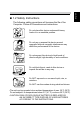
English 1.3 Notes for this Manual CAUTION! Important information that must be followed for safe operation. NOTE : Information for special situations.
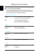
English 1.4 Release History Version Revision Note Date 1.0 First Released 10.
Getting to know the basics English 2.1 Product Specification This User’s Manual provides instructions and illustrations on how to operate this notebook. It is recommended to read this manual carefully before using this notebook. ・Physical Characteristic Dimension 14": 343.57 × 236.6 × 34.5 mm (w/o rubber foot) 15.6": 382 × 255 × 35.9 mm (w/o rubber foot) Weight 14": 1.91kg w/4cells ; 2.0kg w/6cells 15.6": 2.63kg w/4cells ; 2.
English ・Storage HDD 2.5” SATA HDD support Card reader 4 in 1 Card Reader Card ・Optical Device ODD 12.7mm SATA ODD support ・I/O Port DC-in x1 USB (Optional) USB2.0 x 2 + USB3.0 x 1 or USB2.
English ・Display VGA (Optional) Integrated Graphic or Integrated HD Graphic LCD 14.0" HD, 16:9 LED type, resolution 1366 x 768 15.6" HD, 16:9 LED type, resolution 1366 x 768 ・Communication Port LAN 10/100/1000 Mb/Sec Wireless LAN IEEE802.11b/g/n support Bluetooth (Optional) BT 3.0 & 4.0, USB interface support ・Webcam Webcam or HD webcam (Optional) Build-in Webcam module CAUTION : M ODEL IS DESIGNED TO USE WITH THE FOLLOWING AC ADAPTER MODEL ONLY.
English 2.2 Preparing your Computer 1 2 4 3 1 Turn your notebook computer upside down so the bottom is facing up. Insert the battery pack as shown into the battery compartment until it clicks into place. Then slide the lock/unlock latches into the lock position. 2 Plug the AC adapter cable into the DC power connector. 3 To open your notebook computer. 4 Press the power button to turn on your notebook computer.
English 2.3 Product Overview This section provides the description of basic aspects of the notebook. NOTE: The product’s color, I/O port, indicator location, and specification will depend upon the actually shipping product. 2.3.1 Top-Open View The figure of top-open view and description shown below will lead you to browse the main operating area of your notebook. 1 2 8 10 9 3 4 5 6 7 CAUTION: When you are not using the computer, keep the LCD screen closed to protect it from dust.
Function Description 1 Webcam (Optional) The built-in Webcam allows picture taking or video recording. 2 LCD screen Displays of your notebook computer. 3 Power Button Turns on the power of your notebook computer. 4 Keyboard The keyboard provides keys with comfortable travel. 5 Touchpad Touch-sensitive pointing device which functions like the mouse.
English 2.3.2 Bottom Side View Refer to the following illustration to identify the components on this side of the computer. NOTE : T he product’s thermal vent will depend upon the actually shipping product. 1 2 3 Top Side Components Function Description 1 4-in-1 Card Reader SD/MMC/MS/MS Pro Memory Card. 2 Battery lock latch Slide to lock / unlock ( Battery Release). 3 Battery pack Insert the battery into this compartment.
English 2.3.3 Right Side View Refer to the following illustration to identify the components on this side of the computer. 1 3 2 Top Side Components 4 5 Function Description 1 Headphone jack Connects amplified speakers or headphones into this jack. 2 Microphone jack Connects a microphone into this jack. 3 USB Ports Connects an USB device. (such as USB Zip drive, keyboard or mouse) into this jack. 4 Optical drive Slot for inserting a disc. 5 Eject button Ejects the CD/DVD disc.
English 2.3.4 Left Side View Refer to the following illustration to identify the components on this side of the computer. 1 2 3 Top Side Components 4 5 6 Function Description 1 Power Connector Connects the AC adapter into this connector. 2 HDMI Port Connects an external monitor. 3 Network Jack Connects network. 4 External monitor Connects an external monitor. connector 5 USB Port Connects an USB device (such as USB Zip drive, keyboard or mouse) into this jack.
English 2.3.5 Front Side View Refer to the following illustration to identify the components on this side of the computer. 2 1 Top Side Components Function Description 1 Stereo speakers Produce stereo sound. 2 4-in-1 Card Reader SD/MMC/MS/MS Pro Memory Card.
Getting Started English 3.1 AC Adapter Please be noted that it is strongly recommended to connect the AC adapter and use the AC power while using this notebook for the first time. When the AC adapter is connected, the battery is being charged immediately. Note that the AC adapter included in the package is approved for your notebook; using other adapter model may damage either the notebook or other devices attached to it.
English 3.2 Installing the battery pack Insert the battery pack as shown into the battery compartment until it clicks into place. Then slide the lock / unlock latches into the lock position. Unlock Battery pack Lock Battery pack NOTE: N ever attempt to remove the battery pack while the computer is turned ON, as this may result in the loss of working data.
English CAUTION! Only use batteries that are approved by an authorized dealer. All batteries are not the same and therefore should not be treated as such. Using the wrong battery could cause serious damage to your computer and yourself through toxic emissions. CAUTION! Danger of explosion if battery is incorrectly replaced. Replace only with the same or equivalent type recommended by the manufacturer. Dispose of used batteries according to the manufacturer's instructions.
English 3.3 Knowing the Keyboard The following defines the colored hot keys on the Keyboard. The colored commands can only be accessed by first pressing and holding the function key while pressing a key with a colored command. • Keyboard for Windows 7/XP : • Keyboard for Windows 8 : NOTE: The keyboard differs for each territory.
English 3.3.1 ���������������������������������� Windows 7/ XP for keyboard users To activate these functions, press and hold down together with the keys described below: Function Keys Keypad Function Description BT on/off: (Optional) Press this key combination (Fn+Esc) to enter BTon/off mode. “When users would like to upgrade BT2.1 to BT3.0, please power on Fn+F4 WiFi function first, but cannot connect to WLAN AP (WLAN Access Points). Only WLAN module RTL8188CE could support BT3.0 feature.
English Function Keys Keypad Function Description + OSD: (on screen display): Press this key combination (Fn+F5) to show a OSD bar for knowing the definition of function keys. + Touch pad: Press this key combination (Fn+F6) to enter Touch pad mode. + Webcam on/off: Press this key combination (Fn+F7) to enter Webcam on/off mode. + MUTE: Press this key combination (Fn+F8) to enter MUTE mode. + Volume down: Press this key combination (Fn+F9) to enter Volume down mode.
English 3.3.2 ������������������������������ Windows 8 for keyboard users To activate these functions, press and hold down together with the keys described below: Function Keys Keypad Function Description + Suspend: Press this key combination (Fn+F1) to enter sleep mode. + Power Saving: Press this key combination (Fn+F2) to enter power saving mode (CPU will keep the lowest speed). + LCD/CRT/ HDMI mode: Press this key combination (Fn+F3) to enter LCD/CRT/HDMI mode.
English Function Keys Keypad Function Description + Touch pad: Press this key combination (Fn+F6) to enter Touch pad mode. + Webcam on/off: Press this key combination (Fn+F7) to enter Webcam on/off mode. + MUTE: Press this key combination (Fn+F8) to enter MUTE mode. + Volume down: Press this key combination (Fn+F9) to enter Volume down mode. + Volume up: Press this key combination (Fn+F10) to enter Volume up mode.
English 3.4 Using the touchpad The touchpad is a rectangular electronic panel located just below your keyboard. You can use the static-sensitive panel of the touchpad and slide it to move the cursor. You can use the buttons below the touchpad as left and right mouse buttons. Press the left 1 and right 2 buttons located on the edge of the touchpad to make selections and run functions. These two buttons are similar to the left and right buttons on a mouse. Tapping on the touchpad produces similar results.
English 3.4.
English Finger gesture Function Description Play Slide Show Three-finger Up End Slide Show Three-finger Down Page Up Three-finger Left Page Down Three-finger Right 30
English If users do not install Touchpad gesture driver, then they could follow below finger gesture to execute Touchpad scrolling up and down function.
English 3.4.2 ������������ Windows 8 Touchpad Usage Win8 Touch Pad Gesture Modern touchpad gesture: A Windows 8 modern touchpad should support the core touch gestures described in the following table.
English Finger gesture Function Description Swipe in from the right edge Toggle the charms Swipe down from the top edge Toggle the app commands Swipe in from the left edge Switch to last application ( ( ( + + + ) ) + ) 33
BIOS SETUP English 4.1 About BIOS Setup 4.1.1 When to Use BIOS Setup ? You may need to run the BIOS Setup when: ・ An error message appears on the screen during the system booting up and is requested to run SETUP. ・ You want to change the default settings for customized features. ・You want to reload the default BIOS settings. 4.1.2 How to Run BIOS Setup ? To run the BIOS Setup Utility, turn on the notebook and press the [Del] key during the POST procedure.
English 4.2 BIOS Setup Menu Once you enter the BIOS Setup Utility, the Main Menu will appear on the screen. Select the tags to enter the other menus. Info Menu Show System Information about BIOS version,CPU features and Manufacturer. Main Menu Show system overview about memory size, main HDD or ODD and setting of system time and date. Advanced Menu To select the XD feature enable or disable XD feature only work with Intel platform + Windows.
English 4.2.1 Info Menu ・System Information This item provides the information about the firmware, processor, and system memory.
English 4.2.2 Main Menu ・System Date This item allows you to set the system date. The date format is [day:month:date:year]. Use [ENTER], [TAB] or [SHIFT-TAB] to select a field. ・System Time This item allows you to set the system time. The system clock will go on no matter you shut down the PC or get into sleep mode. The time format is [hour:minute:second]. Use [+] or [-] to configure system Time.
English Day Day of the week, from Sun to Sat, which is determined by BIOS (read-only). Month (Month) The month from 01 (January) to 12 (December). Date (Date) The date from 01 to 31. Year (Year) The year can be adjusted by users. ・Memory Information This item provides the information about the system memory. ・Total Memory This allows you to see the total amount of memory.
English 4.2.3 Advanced Menu ・Execute-Disable Bit When disabled, force the XD feature flag to always return 0. ・SATA Mode Selection SATA AHCI mode or IDE mode select. ・Serial ATA Port 0/1 While entering setup,BIOS auto detects the presence of AHCI devices. This displays the status of auto detection of AHCI devices. ・Trusted Computing Turn TPM Enable/Disable. NOTE: Your Computer will reboot during restart in order to change State of TPM.
English 4.2.4 Security Menu ・Change Administrator Password When this item is selected, a message box shall appear on the screen as below: Enter New Password Type a maximum of 20-digit password and press [Enter]. The password typed now will replace any previously set password from CMOS memory. You may also press [ESC] to abandon new password setting.
Note that Administrator Password field allows users to enter and change the settings of the BIOS SETUP UTILITY, while User Password field only allows users to enter the BIOS SETUP UTILITY without having the authorization to make any change. The Password Check item is used to specify the type of BIOS password protection that is implemented.
English 4.2.5 Boot Menu ・Boot Configuration Configure Settings during System Boot. ・LAN Remote Boot: Boot from LAN or not. ・Set Boot Priority (1st/2nd/3rd/..... Boot) Specifies the boot sequence from the available devices. A device enclosed in parenthesis has been disabled in the corresponding type menu. ・USB KEY Drive / UEFI Boot Drive BBS Priorities Specifies the Boot Device Priority sequence.
English 4.2.6 Exit Menu ・Save Changes and Exit Exit system setup after saving the changes. F4 key can be used for this operation. ・Discard Changes and Exit Exit system setup without saving any changes. ESC key can be used for this operation. ・Discard Changes Discards changes done so far to any of the setup questions. F2 key can be used for this operation. ・Restore Defaults Restore/Load Defaults values for all the setup options. F3 key can be used for this operation.