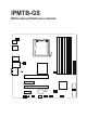
IPMTB-GS Motherboard Reference Guide
Contents Contents.....................................................................................2 Notices.......................................................................................3 Safety information.....................................................................4 Specifications summary...........................................................5 Hardware Installation 1 Before you proceed................................................................................
Notices Federal Communications Commission Statement This device complies with Part 15 of the FCC Rules. Operation is subject to the following two conditions: • • This device may not cause harmful interference, and This device must accept any interference received including interference that may cause undesired operation. This equipment has been tested and found to comply with the limits for a Class B digital device, pursuant to Part 15 of the FCC Rules.
Safety information Electrical safety • • • • • • To prevent electrical shock hazard, disconnect the power cable from the electrical outlet before relocating the system. When adding or removing devices to or from the system, ensure that the power cables for the devices are unplugged before the signal cables are connected. If possible, disconnect all power cables from the existing system before you add a device.
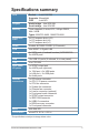
Specifications summary CPU Socket : Intel LGA1366 Supports : Bloomfield FSB : Intel QPI Chipset North bridge : Intel X58 IOH South bridge : Intel ICH10R Memory Triple channels, 6 slots, ECC, 240-pin DDR3, Max. 24GB Types: 800/PC3-6400, 1066/PC3-8500 Expansion slots 2x PCI express slots (x16) 1x PCI express slot (x4) 1x PCI express slot (x1) Audio Realtek ALC888S CODEC (8 Channels) LAN Intel 82567-V Gigabit LAN Storage 4x SATA ports (4 onboad headers) SATA300/150 2x eSATA ports USB 10x USB 2.
Hardware Installation 1 Before you proceed Take note of the following precautions before you install motherboard components or change any motherboard settings. • Unplug the power cord from the wall socket before touching any component. • Use a grounded wrist strap or touch a safely grounded object or to a metal object, such as the power supply case, before handling components to avoid damaging them due to static electricity • Hold components by the edges to avoid touching the ICs on them.
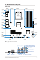
2 Motherboard layout Top view System fan connector Chassis fan connector ATX CPU power connector Internal SPDIF connector CPU fan connector CHASSIS_FAN Memory sockets DIMM5 DIMM2 1394 & USB connectors DIMM6 intel LGA1366 CPU Socket eSATA DIMM3 eSATA ports SYS_FAN DIMM4 SPDIF_OUT1 DIMM1 SPDIF output port LAN & USB connectors LAN+USB ATXPWR 1394+USB ATX_CPU ATX power connector North Bridge Audio connectors SPDIF_OUT2 AUDIO CPU_FAN PCIE16 connector PCIE X16 SLOT1 PCIE4 connector
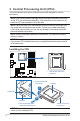
3 Central Processing Unit (CPU) The motherboard comes with a surface mount socket designed for various processors. NOTE: Your boxed processor package should come with installation instructions for the CPU, fan and heatsink assembly. If the instructions in this section do not match the CPU documentation, follow the latter. NOTE: Upon purchase of the motherboard, make sure that the socket cap is on the socket and the socket pins are not bent.
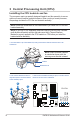
3 Central Processing Unit (CPU) 6. Remove the socket cap from the CPU socket (C). C Load plate B 5. Lift the load plate with your thumb and forefinger (B). A 4. Lift the load lever in the direction of the arrow (A). 7. Position the CPU over the socket as shown. Gold triangle mark Alignment key 8. Close the load plate (A), then push the load lever (B) until it snaps into the retention tab. A Alignment key B Gold triangle mark NOTE: The CPU fits in only one correct orientation.
3 Central Processing Unit (CPU) Installling the CPU heatsink and fan The processor require a specially designed heatsink and fan assembly to ensure optimum thermal condition and performance. When you buy a boxed processor, the package includes the CPU fan and heatsink assembly.
3 Central Processing Unit (CPU) Uninstalling the CPU heatsink and fan 1. Disconnect the CPU fan cable from the connector on the motherboard. 2. Rotate each fastener counterclockwise. 3. Pull up two fasteners at a time in a diagonal sequence to disengage the heatsink and fan assembly from the motherboard. B A A B 4. Remove the heatsink and fan assembly from the motherboard. 5. Rotate each fastener clockwise to reset the orientation.
4 System memory Memory types The motherboard comes with Double Data Rate 3 (DDR3) Dual Inline Memory Modules (DIMM) sockets. WARNING: Only DDR3 RAM modules can be used on this motherboard. The figure illustrates the location of the DDR3 DIMM sockets: 2 1 4 3 6 5 IMPORTANT: Always install DIMMs with the same CAS latency. For optimum compatibility, it is recommended that you obtain memory modules from the same vendor.
4 System memory Possible Memory Configurations System Memory Memory DIMM 2 DIMM 1 DIMM 4 DIMM 3 DIMM 6 DIMM 5 Channel (Ch A, (Ch A, (Ch B, (Ch B, (Ch C, (Ch C, Configuration Black) Blue) Black) Blue) Black) Blue) 2GB Dual - 1GB - 1GB - - 3GB Triple - 1GB - 1GB - 1GB 4GB Dual - 2GB - 2GB - - - 2GB - 1GB - 1GB - 2GB - 2GB - 1GB - 2GB - 2GB - 2GB 1GB 2GB - 2GB - 2GB 2GB 2GB - 2GB - 2GB 1GB 2GB 1GB 2GB 1GB 2GB 2GB 2GB 1GB 2GB - 2GB 2GB 2GB 2G
4 System memory Installing a DIMM WARNING: Unplug the power supply before adding or removing DIMMs or other system components. Failure to do so can cause severe damage to both the motherboard and the components. To install a DIMM: 1. Unlock a DIMM socket by pressing the retaining clips outward. 2. Align a DIMM on the socket such that the notch on the DIMM matches the break on the socket. 3. Firmly insert the DIMM into the socket until the retaining clips snap back in place and the DIMM is properly seated.
5 Expansion slots In the future, you may need to install expansion cards. The following shows the slots and the expansion cards that they support. PCI Express card (x1) PCI Express card (x4) PCI Express card (x16) Installing an expansion card IMPORTANT: Make sure to unplug the power cord before adding or removing expansion cards. Failure to do so may cause you physical injury and damage motherboard components. To install an expansion card: 1.
6 Selectors Clear RTC RAM (CMOS) This selector allows you to clear the Real Time Clock (RTC) RAM in CMOS. You can clear the CMOS memory of date, time, system setup parameters, and passwords by erasing the CMOS RTC RAM data. IMPORTANT: Except when using this function, do not remove the jumper cap from the default position or else there may be a system boot failure! To erase the CMOS RTC RAM user settings: 1. Turn OFF the computer and unplug the power cord. 2.
7 Connectors ATX power connectors (24-pin ATXPOWER and 4-pin ATX_CPU) These connectors are for ATX power supply plugs. The power supply plugs are designed to fit these connectors in only one orientation. Find the proper orientation and push down firmly until the connectors completely fit. NOTE: Do not forget to connect the 4-pin ATX +12 V power plug; otherwise, the system will not boot. NOTE: Use of a PSU with a higher power output is recommended when configuring a system with more power-consuming devices.
7 Connectors Chassis/ System fan connector Connect the fan cables to the fan connectors on the motherboard, making sure that the black wire of each cable matches the ground pin of the connector. CHASSIS_FAN Ground +12V Rotation SYS_FAN Ground +12V Rotation Audio line in connector (optional) This connector allows you to receive stereo audio input from sound sources such as an optical disc drive, a TV tuner, or a specialized audio/sound-processing card.
7 Connectors Serial ATA connectors These connectors are for the Serial ATA signal cables for Serial ATA devices. Ground SATA_RX(+) SATA_RX(-) Ground SATA_TX(-) SATA_TX(+) Ground SATA2 SATA1 Ground SATA_RX(+) SATA_RX(-) Ground SATA_TX(-) SATA_TX(+) Ground SATA4 SATA3 USB connectors These connectors are for USB 2.0 ports. Connect a USB module cable to any of these connectors, then install the module to a slot opening at the back of the system chassis. These USB connectors comply with USB 2.
7 Connectors IEEE 1394 port connector This connector is for a 1394 port. Connect the 1394 cable from the system front panel to this connector. WARNING: Never connect a USB cable to the IEEE 1394 connector. Doing so will damage the motherboard! TPA*(+) Ground TPB*(+) (+)12V TPA*(-) Ground TPB*(-) (+)12V Ground F_1394 Digital Audio connector This connector is for the S/PDIF audio module to allow digital sound output.
7 Connectors Front panel audio connector This connector is for a chassis-mounted front panel audio I/O module that supports HD Audio. LINE*_RTU MIC*_L MIC*_R LINE*_R Ground LINE*_L Ground F_AUDIO_DET# MIC*_RTU F_AUDIO F_AUDIO NOTE: It is recommended that you connect a high-definition front panel audio module to this connector to utilize this motherboard’s high-definition audio capability.
7 Connectors System panel connector These connectors support several chassis-mounted functions. F_PANEL PWR Ground HDLED(+) HDLED(-) Ground Reset NC PLED(+) PLED(-) PLED PWRBTN +HDLED RESET System power LED (2-pin PLED) This 2-pin connector is for the system power LED. Connect the chassis power LED cable to this connector. The system power LED lights up when you turn on the system power. Hard disk drive activity LED (2-pin +HDLED) This 2-pin connector is for the HDD Activity LED.
8 BIOS Setup reference BIOS setup program Just when the computer first starts up (before entering your operating system), press and hold the key to enter the BIOS setup program. (Press to restart if you missed the opportunity.) NOTE: Default BIOS settings apply for most conditions to ensure optimum performance. If this system becomes unstable after changing any BIOS settings, load the default settings to ensure system compatibility and stability.
8 BIOS Setup reference Advanced The Advanced menu items provide advanced information and configuration options to allow enabling or disabling of motherboard chipset features. Main Advanced BIOS SETUP UTILITY Security Boot Power Advanced Settings Exit Configure CPU. CPU Configuration SATA Configuration Onboard Device Settings Hardware Health Configuration Spread Spectrum Configuration Enter F1 F10 ESC v02.
8 BIOS Setup reference Power The power menu items allow you to view or change system power management preferences. Main Advanced Power BIOS SETUP UTILITY Security Boot Exit Select the ACPI ACPI Configuration state used for Suspend mode [Auto] Power On PME# Power On RTC Alarm System Suspend. [Disabled] [Disabled] AC Power Loss [Power On] Enter F1 F10 ESC v02.61 Select Screen Select Item Go to Sub Screen General Help Save and Exit Exit (C) Copyright 1985-2008, American Megatrends, Inc.
8 BIOS Setup reference Security The security items allow you to view or change system security settings. Main Advanced BIOS SETUP UTILITY Security Boot Power Exit Security Settings Install or Change the Supervisor Password :Not Installed User Password :Not Installed password. Change Supervisor Password Change User Password Enter F1 F10 ESC v02.61 Select Screen Select Item Change General Help Save and Exit Exit (C) Copyright 1985-2008, American Megatrends, Inc.
8 BIOS Setup reference Security After you have set a supervisor password, the other items appear to allow you to change other security settings. User Access Level This item allows you to select the access restriction to the Setup items. Configuration options: [No Access] [View Only] [Limited] [Full Access] [No Access] prevents user access to the Setup utility. [View Only] allows access but does not allow change to any field. [Limited] allows changes only to selected fields, such as Date and Time.
8 BIOS Setup reference Boot The Boot menu items allow you to view or change your boot device features. Main Power Advanced BIOS SETUP UTILITY Security Boot Boot Setting Configuration Exit Configure Settings during System Boot. Boot Settings Configuration Boot Device Priority Hard Disk Drives Removable Devices CD/DVD Drives Enter F1 F10 ESC v02.61 Select Screen Select Item Go to Sub Screen General Help Save and Exit Exit (C) Copyright 1985-2008, American Megatrends, Inc.
8 BIOS Setup reference Exit The Exit menu items allow you to load default values for BIOS items, and save or discard your changes to the BIOS items. Main Power Advanced BIOS SETUP UTILITY Security Boot Exit Exit system setup Exit Options Save Changes and Exit Discard Changes and Exit Discard Changes Load Optimal Defaults after saving the changes. F10 key can be used for this operation. Enter F1 F10 ESC v02.
8 BIOS Setup reference Exit Load Optimal Default This option allows you to load the optimal default values for each of the parameters on the Setup items. When you select this option, a confirmation window appears. Select Yes to load the optimal default values. Select Save Changes and Exit or make other changes before saving.