M M77N NC CD DU Ullttrraa FCC Information and Copyright This equipment has been tested and found to comply with the limits of a Class B digital device, pursuant to Part 15 of the FCC Rules. These limits are designed to provide reasonable protection against harmful interference in a residential installation. This equipment generates, uses and can radiate radio frequency energy and, if not installed and used in accordance with the instructions, may cause harmful interference to radio communications.
C Coonntteenntt LAYOUT OF M7NCD ULTRA ................................................................1 COMPONENT INDEX .............................................................................2 ENGLISH ...................................................................................................3 M7NCD Ultra Features............................................................................................... 3 Package contents .....................................................................
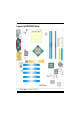
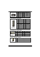
Layout of M7NCD Ultra ※NOTE: ●represents the first pin.
Component Index A. 5V/5VSB Selection for Keyboard and mouse (JKBV1) B. Power Source Selection for USB L. Front USB Header (JUSB1) M. Front USB Header (JUSB2) N. Power Source Selection for USB (JUSBV2) (JUSBV4) C. Back Panel Connector O. Wake On LAN Header (JWOL1) D. Frequency Selection (JCLK3) P. System FAN Header (JSFAN1) E. North Bridge Fan Header (JNFAN1) Q. Clear CMOS Function (JCMOS) F. Accelerated Graphics Port Slot (AGP1) R. Case Open Connector (JC1) S. IDE Connectors (IDE1-2) G.
English M7NCD Ultra Features A. Hardware CPU Provides Socket-462. ® Supports the AMD processor up to XP 3200+. Front Side Bus at 266/333/400 MHz. Chipset North Bridge: nFORCE2 SPP. South Bridge: MCP. High Speed 800Mb/s Hyper-Transport interface to the MCP. Main Memory Supports up to 3 DDR devices. Supports 266/333/400MHz (without ECC) DDR devices. High performance 128 bit DDR400 Twin Bank Memory Architecture. Maximum memory size of 3GB. Super I/O Chip: Winbond W83627HF.
On Board Peripherals a. Rear side 2 serial ports. 1 parallel port. (SPP/EPP/ECP mode) Audio ports in horizontal position. 1 LAN port. (optional) PS/2 mouse and PS/2 keyboard. 2 USB2.0 ports. b. Front Side 1 floppy port supports 2 FDDs with 360K, 720K, 1.2M, 1.44M and 2.88Mbytes. 4 USB2.0 ports. 1 front audio header. Dimensions ATX Form Factor: 24.4cm X 30.4cm (W X L) B. BIOS & Software BIOS Award legal Bios. APM1.2. ACPI. USB Function.
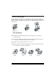
How to setup Jumper The illustration shows how jumpers are setup. When the Jumper cap is placed on pins, the jumper is “close”. If no jumper cap is placed on the pins, the jumper is ”open”. The illustration shows a 3-pin jumper whose pin 1and 2 are “close” when jumper cap is placed on these 2 pins. Jumper close Jumper open Pin1-2 close CPU Installation Step1: Pull the lever sideways away from the socket and then raise the lever up to a 90-degree angle. Step2: Look for the white dot/cut edge.
CPU Fan Header: JCFAN1 1 JCFAN1 Pin No. 1 2 3 Assignment Ground +12V Sense System Fan Header: JSFAN1 1 JSFAN1 Pin No. 1 2 3 Assignment Ground +12V Sense North Bridge Fan Header: JNFAN1 1 JNFAN1 Pin No. 1 2 Assignment Ground +12V DDR DIMM Modules: DIMMB1-2, DIMMA1 For Dual-channel DDR (128-bit) high performance, at least 2 or more DIMM modules must be installed. (It has to be the combination of DIMMA and DIMMB.) With only one DIMM installed, the memory performs only at 64-bit. DRAM Access Time: 2.
Installing DDR Module 1. Unlock a DIMM slot by pressing the retaining clips outward. Align a DIMM on the slot such that the notch on the DIMM matches the break on the slot. 2. Insert the DIMM firmly and vertically into the slot until the retaining chip snap back in place and the Dimm is properly seated. Jumpers, Headers, Connectors & Slots Floppy Disk Connector: FDD1 The motherboard provides a standard floppy disk connector that supports 360K, 720K, 1.2M, 1.44M and 2.88M floppy disk types.
Pin Assignment Pin Assignment 1 Ground 2 TX+ 65 3 2 3 TX- 4 Ground 7 4 1 5 RX- 6 RX+ JSATA1/ JSATA2 7 Ground Power Connectors: JATXPWER1 10 1 20 11 JATXPWER1 PIN Assignment PIN Assignment 1 +3.3V 11 +3.3V 2 +3.
Front Panel Connector: JPANEL1 PWR_LED ON/OFF SLP (+) (+) (-) IR 24 2 JPANEL1 23 1 (+) (-) SPK Pin Assignment 1 +5V 3 NA 5 NA 7 HLED RST Function IR Pin Assignment 2 Function Sleep Control Sleep Speaker 4 Ground Button Connector 6 NA NA Speaker 8 Power LED (+) POWER 9 HDD LED (+) Hard Drive 10 Power LED (+) LED 11 HDD LED (-) LED 12 Power LED (-) 13 Ground Reset 14 Power Button Power-on 15 Reset Control Button 16 Ground Button KEY 17 NA 18 19
Power Source Selection for USB: JUSBV1/ JUSBV2/ JUSBV4 JUSBV1/JUSBV2/ JUSBV4 1 Assignment Description +5V JUSBV1: 5V for JUSB1 port 3 JUSBV2: 5V for JUSBLAN1 port Pin 1-2 close JUSBV4: 5V for JUSB2 port 1 3 +5V Standby Voltage Pin 2-3 close JUSBV1: JUSB1 port powered with standby voltage of 5V JUSBV2: JUSBLAN1 port powered with standby voltage of 5V JUSBV4: JUSB2 port powered with standby voltage of 5V Note: 1.
※ Clear CMOS Procedures: 1. Remove AC power line. 2. Set the jumper to “Pin 2-3 Close”. 3. Wait for five seconds. 4. Set the jumper to “Pin 1-2 Close”. 5. Power on the AC. 6. Reset your desired password or clear the CMOS data.
System Operation Mode: JCLK3 JCLK3 Assignment User Mode (default) 1 (133/ 166/ 200 MHz) Pin 1-2 Close Safe mode 1 (100 MHz) Pin 1-2 Open Note: When overclock function failed and system is unable to boot-up, please follow the instruction below: 1. Turn off the system. 2. Closed the JCLK3 jumper. 3. Turn on the system. 4. Enter CMOS setup menu and load defaults settings. 5. Turn off the system. 6. Open the JCLK3 jumper. 7. Turn on the system.
Deutsch Spezifikationen von M7NCD Ultra A. Hardware CPU Unterstützung für Sockel 462. ® Unterstützung für den AMD Prozessor bis zu XP 3200+. FSB mit 266/333/400 MHz. Chipsatz Northbridge: nFORCE2 SPP. Southbridge: MCP. Hauptspeicher Unterstützung für 3 DDR Geräte. Unterstützung für 266/333/400MHz (ohne ECC) DDR Geräte. 128-Bit High-Performance DDR400 mit der Twin-Bank Architektur. Die maximale Speichergröße ist 3GB. Super I/O Chip: Winbond W83627HF. Serial ATA Chip Chip: VIA VT6420.
Onboard-Peripheriegeräte a. Rückwand 2 Seriell-Ports. 1 parallele Schnittstelle. (SPP/EPP/ECP-Modus) 1 horizontales Audio-Port. 1 LAN-Port. (optional) Unterstützung für PS/2-Maus und PS/2-Tastatur. 2 USB2.0-Ports. b. Vorderseite 1 Floppy-Port mit Unterstützung für 2 Diskettenlaufwerke.(360KB, 720KB, 1.2MB, 1.44MB und 2.88MB) 4 USB2.0-Ports. 1 Audio-Header für die Vonderseite Abmessungen ATX Form-Factor: 24.4 X 30.4cm (W X L) B. BIOS & Software BIOS Award legal Bios. APM1.2. ACPI. USB Funktion.
Einstellung der Jumper Die Abbildung verdeutlicht, wie Jumper eingestellt werden. Pins werden durch die Jumper-Kappe verdeckt, ist der Jumper ”geschlossen”. Keine Pins werden durch die Jumper-Kappe verdeckt, ist der Jumper “geöffnet”. Die Abbiildung zeigt einen 3-Pin Jumper dessen Pin1 und Pin2 ”geschlossen“ sind, bzw. es befindet sich eine Jumper-Kappe auf diesen beiden Pins.
CPU-Lüfter Headers: JCFAN1 1 JCFAN1 Pin 1 2 3 Belegung Masse +12V Sensor System-Lüfter Headers: JSFAN1 1 JSFAN1 Pin 1 2 3 Belegung Masse +12V Sensor Northbridge-Lüfter Header: JNFAN1 1 JNFAN1 Pin 1 2 Belegung Masse +12V DDR-DIMM-Modules: DIMMB1-2, DIMMA1 Für Dual-Kanal DDR (128-Bit) High-Performance, muss man mindestens 2 oder mehr DIMM-Module installieren. (Es ist unbedingt, daß man DIMMA mit DIMMB als ein Paar benutzt.) Wenn man nur ein DIMM installiert, funktioniert der Spreicher nur 64-Bit.
Installation von DDR-Modul 1. Öffnen Sie einen DIMM-Slots, indem Sie die seitlich Chips nach außen drücken. Richten Sie das DIMM-Modul so über dem Slot aus, dass das Modul mit der Kerbe in den Slot passt. 2. Drücken Sie das DIMM-Modul in den Slot, bis die seitlichen Clips zuschnappen und das Modul fest sitzt. Jumpers, Headers, Anschlüsse & Slots Diskettenanschluss: FDD1 Das Motherboard enthält einen standardmäßigen Diskettenanschluss, der 360K-, 720K-, 1.2M-, 1.44M- und 2.88M-Disketten unterstützt.
Dieser Chip bietet zwei Serial-ATA-Kanäle sowie einen Parallel-ATA-Kanal für bis zu zwei Geräte. Es entspriecht der Speczifikation von SATA 1.0.
Wake On LAN Header: JWOL1 1 JWOL1 Pin Belegung 1 +5V_SB 2 Masse 3 Wake-up Stromversorgungsanschluss: JATXPWER1 10 1 20 11 JATXPWR1 PIN Belegung PIN Belegung 1 +3.3V 11 +3.3V 2 +3.
Auswahl von Stromsversorgungsmodi für USB: JUSBV1/ JUSBV2/JUSBV4 JUSBV1/JUSBV2/ JUSBV4 1 Beschreibung Funktion +5V JUSBV1: 5V für JUSB1 3 JUSBV2: 5V für JUSBLAN1 Pin 1-2 geschlossen JUSBV4: 5V für JUSB2 +5V_SB 1 JUSBV1: JUSB1 ist aktiviert durch die reservierte 5V Spannang 3 JUSBV2: JUSBLAN1 ist aktiviert durch die reservierte 5V Spannang Pin 2-3 geschlossen JUSBV4: JUSB2 ist aktiviert durch die reservierte 5V Spannang Anmerkung: 1.
※ Prozeß zum Löschen des CMOS: 1. Ausschalten Sie den AC-Netzstecker. 2. Lassen Sie Pin 2-3 von JCOMS1 geshclossen sein. 3. Bitte warten Sie 15 Sekunden. 4. Lassen Sie Pin 1-2 von JCOMS1 geshclossen sein. 5. Schließen Sie den AC-Netzstecker an. 6. Zurücksetzen Sie das Kennwort nach ihrem Wille oder löschen Sie die CMOS-Daten.
System Operation Modus: JCLK3 JCLK3 Assignment Benutzer Modus (default) 1 (133/ 166 MHz) Pin 1-2 Geöffnet Sicherheit Modus 1 (100 MHz) Pin 1-2 Geschlossen Anmerkung: Wenn “Überspanng Funktion” nicht gelungen ist folgen Sie bitte die Instruktion darunter: 1. Bitte vausschalton Sie den AC-Notzstecker. 2. Lassen Sie Pin 1-2 von JCLK3 geschlossen sein. 3. Schließen Sie den AC-Notzstecker an. 4. Betreten Sie “CMOS Setup Menü” und wählen sie Default-Setting. 5. Ausschalten Sie den AC-Netzstecker wieder.
Watchdog Technology It is important to know that when overclocking, the system can be at a vulnerable state. Therefore, the BIOSTAR Watchdog Technology was designed to protect your PC under dangerous over-clock situations. Any over-clocking that reaches the threshold settings, the Watchdog Technology will disable your system from rebooting in the BIOS setting. Under this circumstance, please power off your PC. After that, press and power on your system simultaneously to restart your system.
StudioFun! Introduction StudioFun! is a media-player based on optimized GNU/Linux distribution. It plays DVD, VCD, MP3, Audio CD and various other known file formats. You can take snapshots of video and customize the saved images as screensavers. You can also store the images on USB mass storage devices like flash disks and USB floppy disks. Hardware Requirements The supported hardware list of StudioFun! grows up every day. So please check the hwreq.
Installation This option will do the basic installation of the distribution. The installation works on pre-installed windows or GNU/Linux distribution. On selecting the ’installation’ option the installer boots and displays a dialog box indicating the space required and waits for a confirmation. Selecting Ok will continue the installation while selecting Cancel will terminate the installation and reboot the machine.
Recovery In case of a MBR corruption, this option should be used. It will automatically probe the hard disk master boot record and find out the installed operating system(s). On success it will re-install the boot loader with correct options in the MBR. Any custom boot loader option specified from other GNU/Linux installations will get over written by the newly probed one. Booting to StudioFun! After Installation is over, remove the CD from the CD-ROM and restart the machine.
After complete boot up, you get to the main Desktop screen. The following section is a complete description of the Desktop application. Desktop This is the main shell of the StudioFun software. It basically comprises of two categories, one is the main "media control" part and the other is the "control panel". Media control The media control part of the Desktop has the following controls: 1. VCD This control will glow whenever a VCD is detected in a DVD/CD-ROM drive.
present in the DVD/CD-ROM drive. 2. DVD This control will glow whenever a DVD is detected in a DVD drive. The DVD will be auto-played only when it is put in to the drive when the Desktop (StudioFun! shell) is up and running, otherwise, the control will simply glow to inform the user about a DVD present in the DVD/CD-ROM. 3. MP3 This control will glow whenever a MP3 is detected in a DVD/CD-ROM drive.
1. Select Region Clicking this icon will invoke the application for selection DVD region settings. Refer to section 5.2 Select DVD Region application for more details. 2. Screensaver Clicking this icon will invoke the screensaver application. Refer to section 5.3 Screensaver for more details. 3. Display Settings Clicking this icon will invoke the application for changing the screen resolutions. Refer to section 5.4, Display Settings for more details. 4.
Software Details XINE XINE is a multimedia player. It plays back Audio CD, DVD, and VCD. It also decodes multimedia files like AVI, MOV, WMV, and MP3 from local disk drives. It interprets many of the most common multimedia formats available - and some of the uncommon formats, too. • Features of Xine a. Skinnable GUI b. Navigation controls (seeking, pause, fast, slow, next chapter, etc) c. On Screen Display (OSD) features d. DVD and external subtitles e. DVD/VCD menus (requires external plugin) f.
a. f. MPEG-Video (.mpv, .m2v) g. MPEG-Audio (.mp2, .mp3) h. WAV (.wav) Video Codecs i. MPEG 1/2 j. MPEG 4 (aka OpenDivX) k. MS MPEG 4 Chapter 5: Software Details 10 l. Windows Media Video 7 m. Motion JPEG • Remote Control support. a. Infrared interface b. User-friendly • Usage of StudioFun! with CelomaChrome skin a. Select VCD button to play a VCD disc b. Select DVD button to play a DVD disc c. Select CDDA button to play a Audio cd d.
l. m. n. o. p. q. r. s. j. Select hide button to hide the control panel of the player k. Select menu button to use menu’s while playing DVD l. Select control button to adjust brightness / color Select setup button to modify the settings of the player Select f.
Screensaver Screensaver The xscreensaver daemon waits until the keyboard and mouse have been idle for a period, and then runs a graphics demo chosen at random. The demo is terminated as soon as there is any mouse or keyboard activity. The xscreensaver-demo program is the graphical user interface to xscreensaver. It lets you tune the various parameters used by the xscreensaver daemon, and browse through the graphics demos.
2. Only one Screen Saver: When user chooses this option, screensaver displays only one graphics demo. 3. Blank Screen Only: When user chooses this option, screensaver only blanks the screen instead of displaying the graphics demo. 4. Disable Screen Saver: When user chooses this option, screensaver is disabled. • Various Graphics Demos XScreensaver comes with various screensaver Chbg: This screensaver displays the images stored in StudioFun! the time gap between images is 5 seconds.
three resolutions. • 640x480 • 800x600 • 1024x768 The current resolution of the Display will be selected by default. It requires restart of the StudioFun to reflect the changes made. File Manager Overview File manger is an utility to copy files from deferent devices to hard disk and vice versa. User can copy files from devices such as, floppy, cdrom and flashdisk to hard disk. And also from hard disk to floppy and flashdisk.
36
Trouble Shooting PROBABLE SOLUTION No power to the system at all Power light don’t * Make sure power cable is securely plugged in illuminate, fan inside power supply does not turn * Replace cable on. Indicator light on keyboard does not turn on * Contact technical support PROBABLE SOLUTION System inoperative. Keyboard lights are on, * Using even pressure on both ends of the power indicator lights are lit, hard drive is DIMM, press down firmly until the module spinning. snaps into place.
Problemlösung MÖGLICHE URSACHE LÖSUNG Das System hat keine Spannungsversorgung. * Versichern Sie sich, dass das Stromkabel richtig Die Stromanzeige leuchtet nicht, der Lüfter im angebracht ist Inneren der Stromversorgung wird nicht * Ersetzen Sie das Stromkabel eingeschaltet. Tastaturleuchten sind nicht an. * Wenden Sie sich an Ihre Kundendienststelle MÖGLICHE URSACHE LÖSUNG Das System funktioniert nicht.
09/29/2003 39