
User Manual


Table Of Contents
- Manual
- Preface
- Chapter 1: Quick Start Guide
- Chapter 2: Storage Devices, Mouse, Audio & Printer
- Chapter 3: Power Management
- Chapter 4: Drivers & Utilities
- What to Install
- Driver Installation
- Manual Driver Installation
- Updating/Reinstalling Individual Drivers
- User Account Control (Win Vista)
- Windows Security Message
- New Hardware Found
- Driver Installation Procedure
- Chipset
- Video
- Audio
- Modem
- LAN
- TouchPad
- Card Reader/ExpressCard
- Hot Key
- Intel MEI Driver
- e-SATA Support
- Optional Drivers
- Wireless LAN
- PC Camera
- 3.5G Module
- Fingerprint Reader Module
- Intel Turbo Memory Technology Driver
- Chapter 5: BIOS Utilities
- Overview
- The Power-On Self Test (POST)
- The Setup Utility
- Main Menu
- Advanced Menu
- Installed O/S (Advanced Menu)
- SATA Mode Selection (Advanced Menu)
- DFOROM (Robson) Support (Advanced Menu > SATA Mode Selection [AHCI]
- Boot-time Diagnostic Screen: (Advanced Menu)
- Legacy OS Boot: (Advanced Menu)
- Reset Configuration Data: (Advanced Menu)
- Power On Boot Beep (Advanced Menu)
- Battery Low Alarm Beep: (Advanced Menu)
- Fan Control (Advanced Menu)
- Security Menu
- Boot Menu
- Exit Menu
- Chapter 6: Upgrading The Computer
- Chapter 7: Modules
- Chapter 8: Troubleshooting
- Appendix A: Interface (Ports & Jacks)
- Appendix B: NVIDIA Video Driver Controls
- Appendix C: Specifications
- Appendix D: Windows XP Information
- DVD Regional Codes
- Windows XP Start Menu & Control Panel
- Audio Features
- Function/Hot Key Indicators
- Video Features
- NVIDIA Video Driver Controls
- Power Management Features
- Configuring the Power Button
- Battery Information
- Driver Installation
- Bluetooth Module
- Wireless LAN Module
- PC Camera Module
- 3.5G Module
- Fingerprint Reader Module
Upgrading The Computer
6 - 10 Upgrading the System Memory (RAM)
6
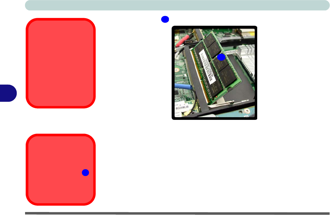
6. The RAM module will pop-up, and you can remove it.
7. Pull the latches to release the second module if necessary.
8. Insert a new module holding it at about a 30° angle and fit th e con n ec to rs firm ly
into the memory socket.
9. The module’s pin alignment will allow it to only fit one way. Make sure the module
is seated as far into the socket as it will go. DO NOT FORCE the module; it should
fit without much pressure.
10. Press the modu le in an d do wn towa r ds the ma in bo ar d until th e soc ke t leve rs click
into place to secure the module.
11. Replace the cover and screws (see Figure 6 - 9).
12. Restart the computer to allow the BIOS will register the new memory configuration
as it starts up.
12
12
Contact Warning
Be careful not to touch
the metal pins on the
module’s connecting
edge. Even the cleanest
hands have oils which
can attract particles, and
degrade the module’s
performance.
Figure 6 - 11
RAM Module
Removal
Fan Cable
Make sure you recon-
nect the fan cable
(see Fig ure 6 - 9) before
screwing down the bay
cover.
8